


Lab 1 : Digital Input and Output with an Arduino
Introduction
In this lab, you’ll connect a digital input circuit and a digital output circuit to a microcontroller. Though this is written for the Arduino microcontroller module, the principles apply to any microcontroller.
Digital input and output are the most fundamental physical connections for any microcontroller. The pins to which you connect the circuits shown here are called General Purpose Input-Output, or GPIO, pins. Even if a given project doesn’t use digital in and out, you’ll often use LEDs and pushbuttons or switches during the development for testing whether everything’s working.
What You’ll Need to Know
To get the most out of this lab, you should be familiar with the following concepts and you should install the Arduino IDE on your computer. You can check how to do so in the links below:
- What is a microcontroller
- Beginning programming terms
- The basics of electricity
- What is a solderless breadboard and how to use one
- Getting Started with Arduino Guide
- Notes on Microcontroller Digital In and Out
Things You’ll Need
Below are the parts you’ll need for this exercise. Click on any image for a larger view.


Related video
The video Video: Digital Output covers the same material as this lab. You’ll see links to it in the lab as you go along, below.
Project 4: One pushbotton two LEDs
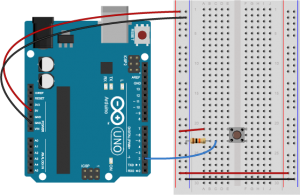
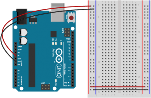
Prepare the breadboard
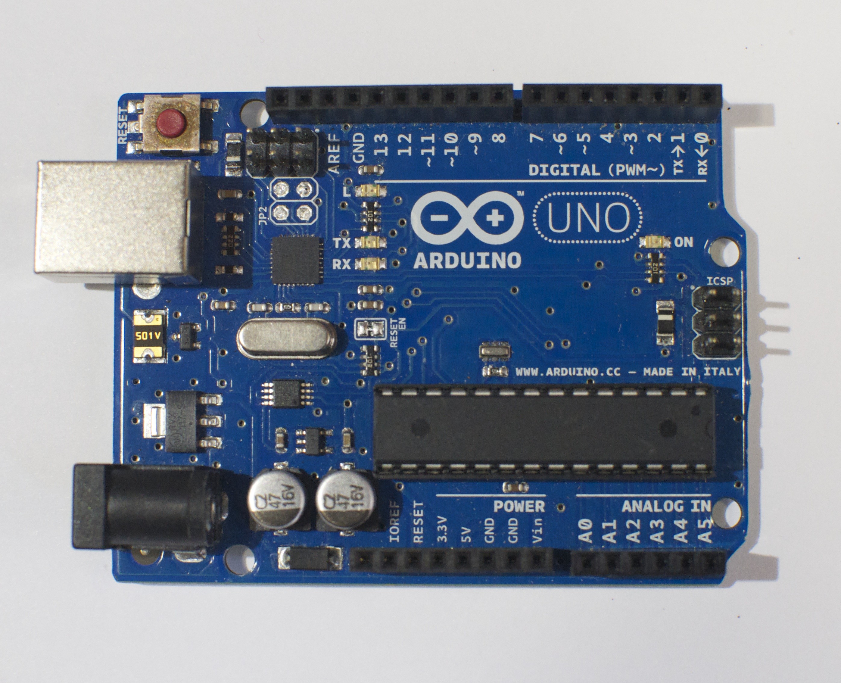
Connect power and ground on the breadboard to power and ground from the microcontroller. On the Arduino module, use the 5V and any of the ground connections:

Made with Fritzing
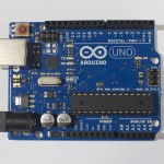
Related video: Overview of the Arduino microcontroller
Related video: Connect Power and Ground using wires
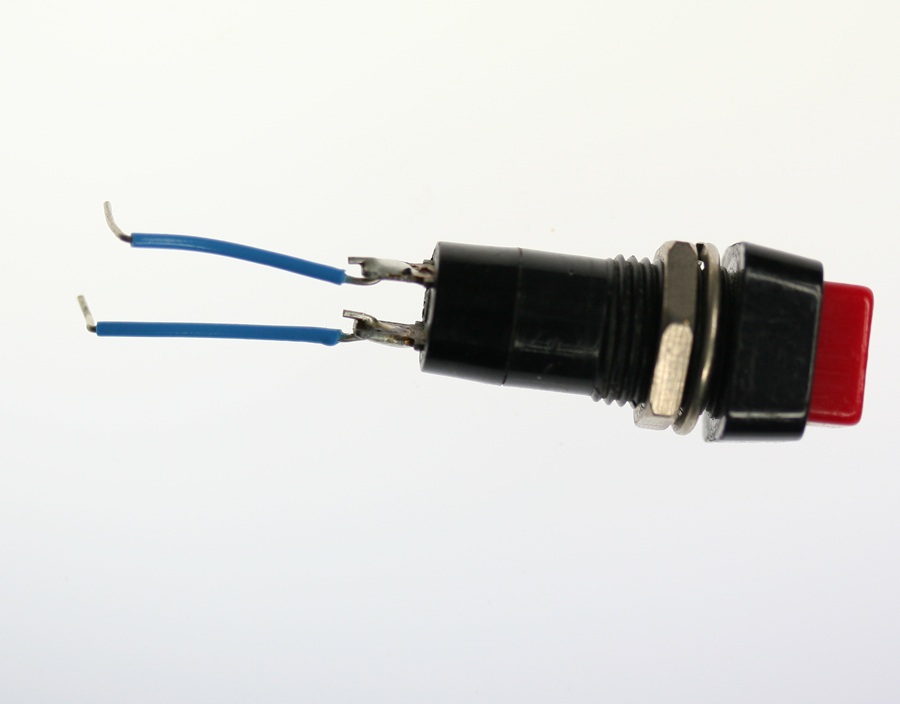
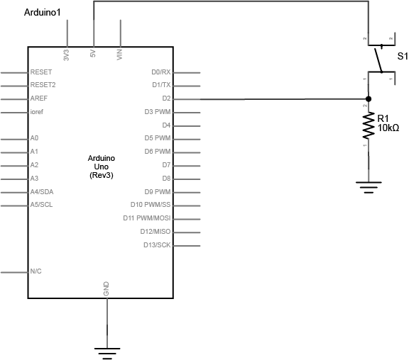
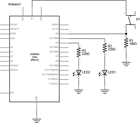
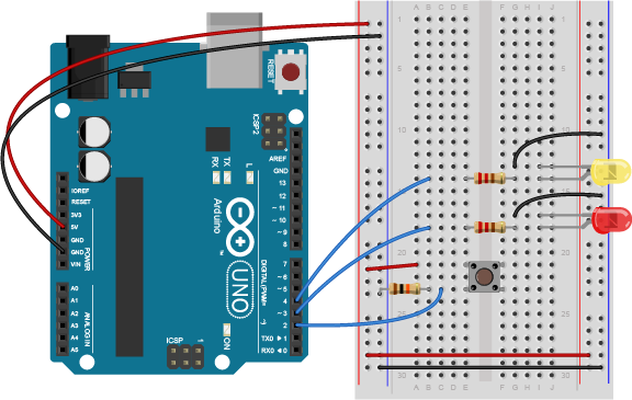
Connect a pushbutton to digital input 2 on the Arduino. The pushbutton shown below is a store-bought momentary pushbutton, but you can use any pushbutton. Try making your own with a couple of pieces of metal as shown in the Switches lab. Related video: Connect a pushbutton to a digital pin
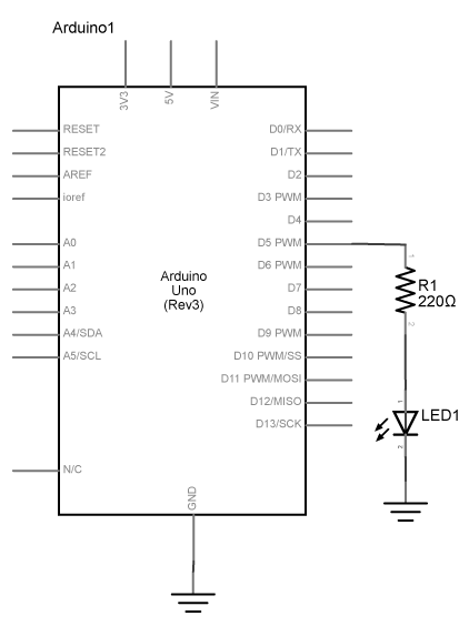
Add Digital Outputs (LEDs)
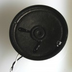
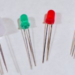
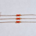
Connect a 220-ohm resistor and an LED in series to digital pin 3 and another to digital pin 4 of the Arduino. If you prefer an audible tone over a blinking LED, you can replace the LEDs with speakers or buzzers.
Note on LED Resistor Values
For the resistor on the LED, the higher the resistor value, the dimmer your LED will be. So 220-ohm resistors give you a nice bright LED, 1-kilohm will make it dimmer, and 10K or higher will likely make it too dim to see. Similarly, higher resistor values attenuate the sound on a speaker, so a resistor value above 220-ohm will make the sound from your speaker or buzzer quieter. Related video: Resistors for an LED
Program the Arduino
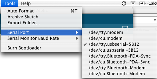
Connect the microcontroller to your computer via USB. When you plug the Arduino into your computer, you’ll find a new serial port in the Tools–>Serial Port menu (for details on installing the software, and USB-to-serial drivers for older Arduino models, see the Arduino Getting Started Guide). In the MacOS, the name look like this: /dev/tty.usbmodem-XXXX (Board Type) where XXXX are part of the board’s unique serial number and Board Type is the board type (for example, Arduino Uno, MKRZero, etc.) In Windows it will be called COM and a number.
Now it’s time to write a program that reads the digital input on pin 2. When the pushbutton is pressed, turn the yellow LED on and the red one off. When the pushbutton is released, turn the red LED on and the yellow LED off.
In your setup() method, you need to set the three pins you’re using as inputs or outputs, appropriately.
void setup() { pinMode(2, INPUT); // set the pushbutton pin to be an input pinMode(3, OUTPUT); // set the yellow LED pin to be an output pinMode(4, OUTPUT); // set the red LED pin to be an output} |
In the main loop, first you need an if-then-else statement to read the pushbutton. If you’re replacing the LED with a buzzer, the code below will work as is. If you’re using a speaker, replace digitalWrite(pinNumber, HIGH); with tone(pinNumber, 440); and digitalWrite(pinNumber, HIGH); with noTone(pinNumber); in the sketch below.
void loop() { // read the pushbutton input: if (digitalRead(2) == HIGH) { // if the pushbutton is closed: digitalWrite(3, HIGH); // turn on the yellow LED digitalWrite(4, LOW); // turn off the red LED } else { // if the switch is open: digitalWrite(3, LOW); // turn off the yellow LED digitalWrite(4, HIGH); // turn on the red LED } } |
Once you’re done with that, you’re ready to compile your sketch and upload it. Click the Verify button to compile your code. Then click the Upload button to upload the program to the module. After a few seconds, the following message will appear in the message pane to tell you the program was uploaded successfully. Related video: Upload the code to the Arduino
Binary sketch size: 5522 bytes (of a 7168 byte maximum)
Press the pushbutton and watch the LEDs change until you get bored. That’s all there is to basic digital input and output!
Get Creative
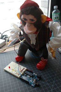
Many projects can be made with just digital input and output. For example, a combination lock is just a series of pushbuttons that have been pushed in a particular sequence. Consider the cymbal-playing monkey below:
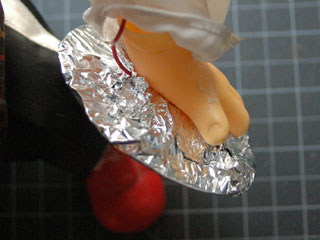
His cymbals can be turned into a switch by lining them with tin foil and screwing wires to them:
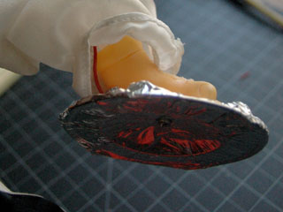
Those wires can be run to a breadboard and used as a switch. Then the microcontroller could be programmed to listen for pattern of cymbal crashes, and if it sees that pattern, to open a lock by turning on a digital output.
Now come up with your own physical interface for a combination lock, for example.
Lab 3: Analog In with an Arduino
Introduction
In this lab, you’ll learn how to connect a variable resistor to a microcontroller and read it as an analog input. You’ll be able to read changing conditions from the physical world and convert them to changing variables in a program.
Many of the most useful sensors you might connect to a microcontroller are analog input sensors. They deliver a variable voltage, which you read on the analog input pins using the analogRead() command.
What You’ll Need to Know
To get the most out of this lab, you should be familiar with the following concepts and you should install the Arduino IDE on your computer. You can check how to do so in the links below:
- What is a microcontroller
- Beginning programming terms
- What variables are
- The basics of electricity
- What is a solderless breadboard
- The basics of Digital input and output with Arduino
Things You’ll Need
For this lab you will need the following parts:
Project 5: Control an LED with a potentiometer
Prepare the breadboard
Conect power and ground on the breadboard to power and ground from the microcontroller. On the Arduino module, use the 5V and any of the ground connections:
Made with Fritzing
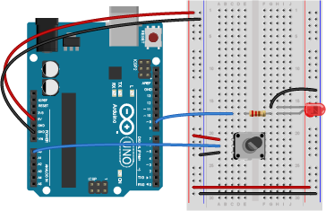
Add a Potentiometer and LED
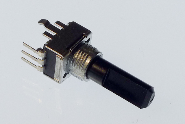
Connect the wiper of a potentiometer to analog in pin 0 of the module and its outer connections to voltage and ground. Connect a 220-ohm resistor to digital pin 9. You can replace the LED with a speaker if you prefer audible output. Connect the anode of an LED to the other side of the resistor, and the cathode to ground as shown below:
Related Video: Potentiometer schematic
Program the Module
Now that you have the board wired correctly, program your Arduino as follows:
First, establish some global variables: one to hold the value returned by the potentiometer, and another to hold the brightness value. Make a global constant to give the LED’s pin number a name.
const int ledPin = 9; // pin that the LED is attached toint analogValue = 0; // value read from the potint brightness = 0; // PWM pin that the LED is on. |
In the setup() method, initialize serial communications at 9600 bits per second, and set the LED’s pin to be an output.
void setup() { // initialize serial communications at 9600 bps: Serial.begin(9600); // declare the led pin as an output: pinMode(ledPin, OUTPUT);} |
In the main loop, read the analog value using analogRead() and put the result into the variable that holds the analog value. Then divide the analog value by 4 to get it into a range from 0 to 255. Then use the analogWrite() command to face the LED. Then print out the brightness value. If you’re replacing the LED with a speaker, replace analogWrite(pinNumber, brightness); with tone(pinNumber, brightness*10);
void loop() { analogValue = analogRead(A0); // read the pot value brightness = analogValue /4; //divide by 4 to fit in a byte analogWrite(ledPin, brightness); // PWM the LED with the brightness value Serial.println(brightness); // print the brightness value back to the serial monitor} |
When you run this code, the LED should dim up and down as you turn the pot, and the brightness value should show up in the serial monitor.
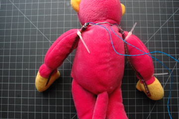
Project 6: Other variable resistors
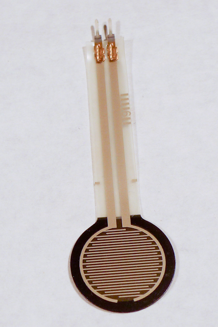
You can use many different types of variable resistors for analog input. For example, the pink monkey in the photo below has his arms wired with flex sensors. These sensors change their resistance as they are flexed. When the monkey’s arms move up and down, the values of the flex sensors change the brightness of two LEDs. The same values could be used to control servo motors, change the frequency on a speaker, or move servo motors.
Related Video: Wiring an FSR (force sensitive resistor)
Related Video: Wiring a photocell to measure light
Note on Soldering Sensor Leads
Flex sensors and force-sensing resistors melt easily, so unless you are very quick with a soldering iron, it’s risky to solder directly to their leads. Here are three better solutions:
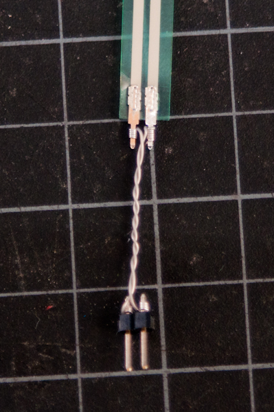
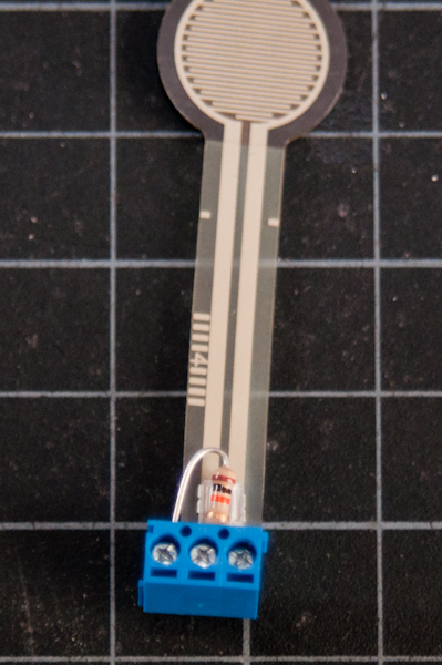
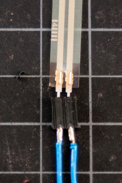
,,
Use wire wrapping wire and a wire wrapping tool,Use screw terminals (if you have a row of three you can attach the fixed resistor as well),Use female headers
Adafruit has a good FSR tutorial as well.
Here’s an example circuit much like the pink monkey circuit above, but with force-sensing resistors instead of flex sensors. Two force-sensing resistors are connected to analog pins 0 and 1 of the Arduino. Two LEDs are connected to digital pins 9 and 10 through 220-ohm resistors.
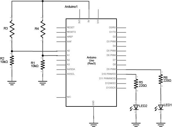

The circuit above works for any variable resistor. You could replace the force-sensing resistors with flex sensors to use the monkey toy above with this circuit. Two resistors placed in series like this are called a voltage divider. There are two voltage dividers in the circuit shown, one on analog in 0 and one on analog in 1. The fixed resistor in each circuit should have the same order of magnitude as the variable resistor’s range. For example, if you’re using a flex sensor with a range of 50 – 100 kilohms, you might use a 47-kilohm or a 100-kilohm fixed resistor. If you’re using a force sensing resistor that goes from infinity ohms to 10 ohms, but most of its range is between 10 kilohms and 10 ohms, you might use a 10-kilohm fixed resistor.
The code above assumed you were using a potentiometer, which always gives the full range of analog input, which is 0 to 1023. Dividing by 4 gives you a range of 0 to 255, which is the full output range of the analogWrite() command. The voltage divider circuit, on the other hand, can’t give you the full range. The fixed resistor in the circuit limits the range. You’ll need to modify the code or the resistor if you want a different range.
Finding Your Sensor Range
Related Video: Use map() to detect the sensor’s state
To find out your range, open the serial monitor and watch the printout as you press the FSR or flex the flex sensor. Note the maximum value and the minimum value. Then you can map the range that the sensor actually gives as input to the range that the LED needs as output.
For example, if your photocell gives a range from 400 to 900, you’d do this:
// map the sensor value from the input range (400 - 900, for example) to the output range (0-255):int brightness = map(sensorValue, 400, 900, 0, 255);analogWrite(ledPin, brightness); |
You know that the maximum input range of any analog input is from 0 to 5 volts. So if you wanted to know the voltage on an analog input pin at any point, you could do some math to extrapolate it in your loop() like so:
void loop() { // read the sensor on analog pin 0: int sensorValue = analogRead(A0); // Convert the analog reading (which goes from 0 - 1023) to a voltage (0 - 5V): float voltage = sensorValue * (5.0 / 1023.0); // print out the value you read: Serial.println(voltage);} |
Now write a sketch to control the red LED with the first sensor (we’ll call it the right hand sensor) and the green LED with the second sensor (we’ll call it the left hand sensor). First, make two constants for the LED pin numbers, and two variables for the left and right sensor values.
const int redLED = 10; // pin that the red LED is onconst int greenLED = 11; // pin that the green LED is onint rightSensorValue = 0; // value read from the right analog sensorint leftSensorValue = 0; // value read from the left analog sensor |
In the setup(), initialize serial communication at 9600 bits per second, and make the LED pins outputs.
void setup() { // initialize serial communications at 9600 bps: Serial.begin(9600); // declare the led pins as outputs: pinMode(redLED, OUTPUT); pinMode(greenLED, OUTPUT);} |
Start the main loop by reading the right sensor using analogRead(). Map it to a range from 0 to 255. Then use analogWrite() to set the brightness of the LED from the mapped value. Print the sensor value out as well.
void loop() { rightSensorValue = analogRead(A0); // read the pot value // map the sensor value from the input range (400 - 900, for example) // to the output range (0-255). Change the values 400 and 900 below // to match the range your analog input gives: int brightness = map(rightSensorValue, 400, 900, 0, 255); analogWrite(redLED, brightness); // set the LED brightness with the result Serial.println(rightSensorValue); // print the sensor value back to the serial monitor |
Finish the main loop by doing the same thing with the left sensor and the green LED.
// now do the same for the other sensor and LED: leftSensorValue = analogRead(A1); // read the pot value // map the sensor value to the brightness again. No need to // declare the variable again, since you did so above: brightness = map(leftSensorValue, 400, 900, 0, 255); analogWrite(greenLED, brightness); // set the LED brightness with the result Serial.println(leftSensorValue); // print the sensor value back to the serial monitor} |
Mapping works for audible tones as well. Human hearing is in a range from 20Hz to 20 kHz, with 100 – 10000 Hz being a reasonable middle ground so if your input is in a range from 0 to 255, you can quickly get audible tones by mapping like so:
int pitch = map(input, 0, 255, 100, 10000);
Get creative
This is just a suggestion for a short project. It’s not a requirement for the class homework.
Make a luv-o-meter with analog inputs. A luv-o-meter is a device that measures a person’s potential to be a lover, and displays it on a graph of lights. In gaming arcades, the luv-o-meter is usually a handle that a person grips, and his or her grip is measured either for its strength or its sweatiness. But your luv-o-meter can measure any analog physical quantity that you want, providing you have a sensor for it. Make sure the display is clear, so the participant knows what it means, and make sure it is responsive.
Source : https://itp.nyu.edu/physcomp/labs/