Afin de travailler avec des exemples concrets que vous pouvez suivre, nous allons d'abord créer deux tables temporaires nommées "personnes" et "salaire", puis ces deux tables temporaires seront utilisées pour le reste de l'exercice. L'avantage de cette approche est que vous pouvez copier et coller la partie de création de tableau, puis vous entraîner le long des étapes suivantes pour maximiser l'opportunité d'apprentissage. Veuillez noter que vous n'avez pas besoin de comprendre la partie création de table du travail à ce stade. La partie que vous devez comprendre commence après cela.
Alors, allez-y, copiez et collez ce qui suit dans votre outil SQL préféré et appuyez sur Exécuter.
Voyons maintenant ce que nous avons créé dans les deux tables temporaires ci-dessus. Je vais les présenter sous forme de questions et de réponses afin que vous puissiez également essayer de résoudre chaque question en premier, avant de regarder la réponse que j'ai fournie. Ce que j'ai fourni n'est qu'une façon de résoudre ces questions - généralement, il y a plus d'une bonne façon d'arriver à la même réponse.
Q1 : Récupérez toutes les données disponibles dans le tableau people.
A1 :
En général, je vais d'abord fournir les réponses, puis expliquer ce qui s'est passé et comment fonctionnent différents concepts SQL, soit sous la même question, soit sous la suivante. Par exemple, Q2 expliquera ce qui s'est passé en Q1.
SELECT * FROM personnes ;
Résultats:
salaryEt pour référence future, voici à quoi ressemble le tableau , en utilisant ce qui suit :
SELECT * FROM salaire ;
Conseil de pro : à ce stade, je vous suggère de prendre un instantané de ces deux tableaux. J'ai ajouté des instructions ci-dessous sur la façon de prendre un instantané. Vous voudrez vous référer aux tableaux pour écrire des requêtes à l'avenir et faire défiler de haut en bas dans cet article pour trouver que ces deux tableaux ne seront pas amusants. Pour plus de commodité, j'ai inclus des instructions sur la façon de prendre un instantané sur Mac et Windows :
Utilisateurs Mac — Appuyez sur ces trois touches et maintenez-les enfoncées : Maj, Commande et 4, puis sélectionnez la zone pour l'instantané. Si vous ne souhaitez pas sélectionner manuellement la zone d'instantané, appuyez simultanément sur Maj, Commande et 3 pour créer un écran d'impression.
Utilisateurs Windows - Appuyez sur ces trois touches ensemble : Touche Windows + Maj + S, puis créez un instantané à l'aide de l'outil Snip and Sketch (je suis sur un Mac, donc cela est basé sur une recherche Google - j'espère que cela fonctionnera).
Q2 : Expliquez ce qui s'est passé dans la requête précédente.
A2 : SELECTl'instruction est utilisée pour sélectionner des données à partir d'une base de données donnée (c'est-à-dire une table). FROMest utilisé pour indiquer dans quelle base de données les données doivent être sélectionnées ("personnes" dans cet exemple). Et enfin *dit simplement tout sélectionner dans cette base de données.
Q3 : Afficher uniquement les données des colonnes suivantes : ['name', 'gender', 'job_title'].
A3 :
SELECT nom, sexe, job_title FROM personnes ;
Résultats:
Celui-ci était simple - nous pouvons indiquer explicitement si les colonnes doivent être sélectionnées.
Q4 : Quelles personnes travaillent à New York ?
A4 :
SELECT nom FROM personnes WHERE emplacement = 'new_york';
Résultats:
Comme le montre cet exemple, nous pouvons filtrer les résultats à l'aide de WHERE.
3. Agrégations
Les agrégations nous aident à effectuer des analyses de base sur les données. Les exemples incluent COUNT(), MAX(), MIN(), AVG()et SUM().
Q5 : Combien de personnes vivent à Seattle ou à Phonenix ?
A5 :
SELECT count(person_id) FROM people WHERE location IN ('seattle', 'phoenix');
Résultats:
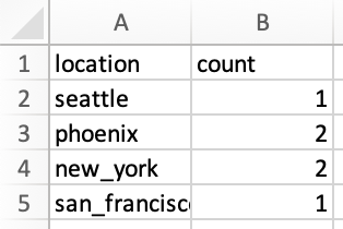
Q6 : Combien d'individus vivent dans chacune des villes ?
A6 :
SELECT location, count(person_id) FROM personnes GROUP BY location ;
Résultats:
Nous savions déjà ce que COUNT()c'était à partir de la question précédente, mais maintenant il y a aussi un nouveau concept à la fin de la requête. GROUP BYL'instruction regroupe des lignes de données avec les mêmes valeurs et est utilisée avec des fonctions d'agrégation, telles que COUNT(), MAX(), MIN(), AVG()et SUM().
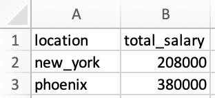
Q7 : Quel est le total des salaires à Phoenix et à New York ?
A7 :
SELECT location, SUM(salary) AS total_salary FROM people WHERE location = 'phoenix' OR location = 'new_york' GROUP BY location;
Résultats:
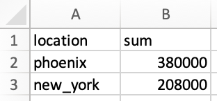
Il y a deux nouveaux apprentissages dans cet exemple. La première est que dans cet exemple, nous avons attribué un alias à la SUM()colonne et la colonne résultante est maintenant nommée total_salary. Si nous ne l'avions pas fait, la colonne aurait ressemblé à ceci :
Le deuxième apprentissage est une approche alternative. Notez que dans le WHERE, nous utilisons OR, qui détermine locationpeut être phoenixou new_york. Alternativement, nous aurions pu utiliser location IN ('phoenix', 'new_york'), similaire à l'approche que nous avons utilisée dans Q5. Cela ne change pas les résultats et est simplement une approche alternative.
4. Jointures
C'est l'une des fonctionnalités les plus utiles. Ce. aide à visualiser les données lorsque vous essayez de comprendre les requêtes. Regardons d'abord un exemple, puis j'expliquerai ce qui se passe.
Q8 : Montrez-moi les noms des personnes, leurs emplacements et leurs salaires, ainsi que le salaire moyen dans chaque emplacement.
R8 : Notez qu'il s'agit d'un nouveau type de question que nous n'avions pas abordé auparavant. Les noms individuels, les emplacements et leurs salaires sont disponibles dans le tableau peopletandis que le salaire moyen par emplacement est disponible dans le tableau salary. Ce dont nous avons besoin, c'est de JOINces deux tables ensemble, ce qui est possible car les deux tables ont le nom des villes en commun (bien que les colonnes soient nommées locationdans peopleet citydans salary). La façon dont nous structurons cela est la suivante :
SELECT p.name, p.location, p.salary, s.average_salary FROM personnes p LEFT JOIN salaire s ON p.location = s.city ;
Résultats:
Alors que s'est-il passé exactement ? Regardons la jointure de plus près :
FROM personnes p LEFT JOIN salaire s ON p.lieu = s.ville
Ce qui précède dit que regarder table peoplepuis le joindre à table salary. Ensuite, nous devons indiquer les colonnes de chaque table qui partagent les mêmes valeurs (imaginez assembler ces deux tables uniquement là où il y a des valeurs communes dans ces deux colonnes particulières). Les colonnes avec des valeurs mutuelles sont locationfrom peopleet cityfrom salary. Enfin, nous utilisons ici le concept d'alias. Par exemple, table peoplea maintenant un alias de p, tandis que table salarya un alias de s. Lorsque nous voulons indiquer la colonne locationde people, nous pouvons soit indiquer cela comme people.locationou p.location. Il en va de même pour la façon dont nous indiquons la colonne cityà partir salaryde s.city. Notez que la structure est toujours aussitable_name.column_name. Enfin, nous avons utilisé a LEFT JOINdans cet exemple. Ci-dessous, je vais discuter de ce que cela signifie et des autres moyens de rejoindre des tables.
Comme mentionné, nous avons utilisé a LEFT JOINdans cet exemple. Il est utile d'avoir l'image ci-dessous à l'esprit lorsque l'on réfléchit à son JOINfonctionnement.
Voici quelques-uns des JOINtypes les plus courants :
JOINor INNER JOIN: Renvoie les données qui ont des valeurs correspondantes dans les tables de gauche et de droite.
LEFT JOINor LEFT OUTER JOIN: Renvoie les données de la table de gauche et toutes les données correspondantes de la table de droite.
RIGHT JOINou RIGHT OUTER JOIN: C'est le revers du LEFT JOIN. Il renvoie les données de la table de droite et toutes les données correspondantes de la table de gauche.
FULL JOINor FULL OUTER JOIN: Renvoie toutes les données de la table de gauche ou de droite lorsqu'il y a une correspondance entre les deux
5. Conditionnels
Q9 : Créez une nouvelle colonne dans peoplequi décompose les titres de poste en technologies et non technologies. Renvoie uniquement les noms, les intitulés de poste, la nouvelle catégorie nommée as job_groupet les salaires.
A9 : Afin de répondre à cette question, nous devons d'abord voir quels titres de poste uniques sont disponibles en peopleutilisant la requête suivante :
SELECT DISTINCT job_title FROM personnes ;
Notez qu'il DISTINCTs'agit de l'instruction qui a été ajoutée pour SELECTne renvoyer que des valeurs uniques (ou distinctes) dans cette colonne, comme le montrent les résultats ci-dessous :
Maintenant que nous savons quels titres de poste existent, nous pouvons les décomposer en technologies et non technologies, comme indiqué. Pour cet exercice, utilisez votre meilleur jugement pour déterminer quel rôle est technique et ce qui n'est pas technique - une partie importante est d'apprendre à implémenter cette logique dans la requête. Par exemple, financial_analystest un rôle non technique, tandis que data_scientistest un rôle technique. La requête suivante fait exactement cela :
SELECT name, job_title, CASE WHEN job_title IN ('software_developer', 'data_scientist') THEN 'tech' WHEN job_title IN ('financial_analyst', 'physician') THEN 'non-tech' ELSE job_title END AS job_group, salaire FROM people ;
Résultats:
Parlons du fonctionnement de l' CASEexpression en regardant de plus près ce que nous avons fait pour cette question :
CASE WHEN job_title IN ('software_developer', 'data_scientist') THEN 'tech' WHEN job_title IN ('financial_analyst', 'physician') THEN 'non-tech' ELSE job_title END AS job_group,
Afin de mettre en œuvre cette logique, nous commençons d'abord par l' CASEexpression puis identifions les conditions, en utilisant WHEN, telles que :
WHEN job_title IN ('software_developer', 'data_scientist') THEN 'tech'
Le script ci-dessus examine d'abord la colonne job_title, et si la valeur de cette colonne pour une ligne est soit software_developerou data_scientist, il affiche ensuite tech. La même logique s'applique pour la non-techcatégorie.
Alors il y a ELSE job_title. Cette clause indique que si une valeur est rencontrée dans la colonne qui n'était pas couverte par les WHENconditions ci-dessus, renvoie la valeur qui existe dans la colonne job_title. Par exemple, si nous avions une ligne dans la colonne job_titleavec la valeur de chef, car chefne faisait pas partie de celles que nous avions incluses dans les WHENconditions (c'est-à-dire software_developer, data_scientist, financial_analystet physician), alors cette clause renverrait la valeur d'origine dans la colonne job_title, qui était chef.
La dernière partie du script est END AS job_group. CASEL' expression se termine par un ENDet AS job_groupest l'alias donné à la colonne résultante. C'est pourquoi la colonne est nommée job_groupdans le tableau des résultats.
Conseil de pro : l'ordre des instructions conditionnelles, en commençant parWHEN, est important. Une fois qu'une condition est vraie, il arrête de lire le reste des conditions et renvoie le résultat. Si aucune des conditions n'est remplie, elle renvoie la valeur de laELSEclause.
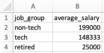
Q10 : Qu'est-ce qui job_grouprapporte le plus d'argent en moyenne ? Ordonnez les résultats du plus élevé au plus bas job_group.
A10 : J'inclurai deux approches pour répondre à cette question, chacune introduira de nouveaux concepts. Je vais d'abord couvrir une approche pour montrer comment utiliser FROMdirectement sur une sortie d'une requête, puis je couvrirai une approche différente pour démontrer l'application de WITHla clause.
Approche 1 :
SELECT job_group, AVG(salary) AS average_salary FROM ( SELECT person_id, CASE WHEN job_title IN ('software_developer', 'data_scientist') THEN 'tech' WHEN job_title IN ('financial_analyst', 'physician') THEN 'non-tech' ELSE titre_emploi END AS groupe_emploi, salaire FROM personnes ) GROUP BY groupe_emploi ORDER BY salaire_moyen DESC ;
Résultats:
Alors que s'est-il passé exactement ? Dans le passé, nous incluions toujours le nom d'une table après FROM, mais le nouveau concept ici est que nous pouvons également inclure une requête interne au lieu du nom de la table. Ce qui se passe, c'est que la requête interne après FROMest d'abord exécutée, puis les résultats sont utilisés comme table temporaire pour sélectionner des données dans la requête externe.
Approche 2 :
Je commencerai par inclure la requête utilisée dans cette approche, puis j'expliquerai chacune des étapes de la requête. Commençons d'abord par la requête :
WITH count_table AS( SELECT CASE WHEN job_title IN ('software_developer', 'data_scientist') THEN 'tech' WHEN job_title IN ('financial_analyst', 'physician') THEN 'non-tech' ELSE job_title END AS job_group, count(person_id) as total_count FROM people GROUP BY 1 ), total_salary_table AS( SELECT CASE WHEN job_title IN ('software_developer', 'data_scientist') THEN 'tech' WHEN job_title IN ('financial_analyst', 'physician') THEN 'non-tech' ELSE job_title END AS job_group, SUM(salaire) as total_salary FROM people GROUP BY 1 ) SELECT ct.job_group, tst.total_salary / ct.total_count as average_salary FROM count_table ct INNER JOIN total_salary_table tst ON ct.job_group = tst.job_group ORDER BY average_salary DESC ;
Regardons maintenant de plus près ce qui s'est passé.
Nous allons d'abord créer une table temporaire à l'aide de la WITHclause, nommée count_table. Ce tableau temporaire indique le nombre d'individus dans chaque job_group, comme indiqué ci-dessous :
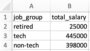
Ensuite, nous allons créer une deuxième table temporaire nommée total_salary_tablequi affiche le salaire total de chaque job_group, comme indiqué ci-dessous :
Maintenant que nous avons ces deux tableaux, nous pouvons les joindre pour trouver le salaire moyen de chacun job_group, comme suit :
Les résultats ici correspondent aux résultats de l'approche 1 comme prévu.
6. Fonctions de la fenêtre
Ces fonctions sont plus difficiles à visualiser au départ, alors ne soyez pas déçu si vous ne l'obtenez pas tout de suite. Passez en revue quelques exemples et vous commencerez à mieux les comprendre. Nous les incluons généralement dans nos entretiens, je vous recommande donc de les comprendre et de les mettre en pratique.
Les fonctions de fenêtre effectuent généralement un calcul sur un ensemble de lignes de table qui sont liées d'une manière ou d'une autre. En d'autres termes, ils ressemblent en quelque sorte à des agrégations avec quelques mises en garde. Contrairement aux agrégations, les fonctions de fenêtre n'entraînent pas le regroupement des lignes. Cela deviendra plus clair avec des exemples.
Voici quelques exemples de fonctions de fenêtre : COUNT(), AVG(), SUM(), ROW_NUMBER(), RANK(), DENSE_RANK(), LAG, et LEADet elles sont structurées comme suit :
fonction_fenêtre(nom_colonne) OVER ( PARTITION BY nom_colonne ORDER BY nom_colonne ROWS BETWEEN UNBOUNDED PRECEDING AND UNBOUNDED FOLLOWING ) AS output_alias;
L'exemple ci-dessus montre les éléments les plus courants de la structure des fonctions de fenêtre, mais ils ne sont pas tous nécessaires. Je sais que jusqu'à présent, cela n'a pas de sens, alors examinons certains d'entre eux dans la pratique pour mieux les comprendre.
Q11 : Créez un classement des salaires dans l'ensemble et également par sexe, du salaire le plus élevé au salaire le plus bas.
A11 :
SELECT nom, sexe, salaire, RANK() OVER( ORDER BY salaire DESC ) AS salaire_rang_overall, RANK() OVER( PARTITION BY sexe ORDER BY salaire DESC ) AS salaire_rang_by_sexe FROM personnes ORDER BY salaire_rang_overall, salaire_rang_by_sexe ;
Résultats:
Comme vous pouvez le voir dans les résultats, en utilisant RANK()la fonction de fenêtre, nous avons pu classer les salaires à la fois dans une perspective globale et également dans chacune des catégories masculines ou féminines. À l'intérieur du OVER(), nous avons indiqué que nous voulions que le classement soit décomposé (ou «partitionné») par genderet également trié par salaire du plus élevé au plus bas en ajoutant ORDER BY salary DESC.
Q12 : Créer une somme cumulée de chaque salaire à la fois globalement (c'est-à-dire que la somme à la ligne 2 doit être la ligne 1 + la ligne 2, la somme à la ligne 3 doit être la somme de la ligne 1 + la ligne 2 + la ligne 3, et ainsi de suite) et aussi par sexe , classés par âge (du plus vieux au plus jeune). Incluez également une colonne indiquant le salaire total à chaque ligne.
A12 :
SELECT nom, sexe, année_de_naissance, salaire, SUM(salaire) OVER( ORDER BY rows_année_de_naissance entre UNBOUNDED PRECEDING And CURRENT ROW ) AS running_total_salary_overall, SUM(salary) OVER( PARTITION BY gender ORDER BY birth_year ROWS between UNBOUNDED PRECEDING And CURRENT ROW ) AS running_total_salary_by_gender, SUM(salary) OVER( ORDER BY birth_year ROWS between UNBOUNDED PRECEDING And UNBOUNDED FOLLOWING ) AS total_salary FROM people ORDER BY running_total_salary_overall, running_total_salary_by_gender ;
Résultats:
Une fois que vous aurez parcouru les explications ci-dessous et que vous les aurez comparées aux résultats, je suis sûr que vous apprécierez également la puissance des fonctions de fenêtre.
Celui-ci a utilisé de nouvelles déclarations, alors regardons-les de plus près. Regardons d'abord ce qui suit :
SUM(salary) OVER( ORDER BY birth_year ROWS between UNBOUNDED PRECEDING And CURRENT ROW ) AS running_total_salary_overall,
SUM(salary)additionne simplement les salaires, mais la façon dont les salaires doivent être additionnés est la partie la plus intéressante et est indiquée dans la OVER()déclaration. Tout d'abord, les salaires sont triés par année de naissance des individus du plus bas au plus élevé, comme indiqué dans ORDER BY birth_year, (l'absence de DESCnous indique que c'est dans un ordre croissant). Indique ensuite ROWScomment le SUM()doit être appliqué à ces lignes de données. Dans ce cas, la sommation est appliquée à toutes les lignes avant chaque ligne ( UNBOUNDED PRECEDING) jusqu'à et y compris la ligne elle-même ( CURRENT ROW).
Et si nous voulions que la somme de chaque ligne inclue tout ce qui précède et aussi tout ce qui suit cette ligne spécifique ? Cela peut être accompli par ce qui suit :
LIGNES entre UNBOUNDED PRECEDING et UNBOUNDED FOLLOWING
Cette structure a été utilisée pour calculer le total_salarydans la partie suivante de la requête et vous pouvez voir dans la section des résultats :
SUM(salaire) OVER( ORDER BY birth_year ROWS between UNBOUNDED PRECEDING And UNBOUNDED FOLLOWING ) AS total_salary
Étant donné que pour chaque ligne, nous voulions avoir la somme de toutes les lignes avant et après une ligne donnée, nous avons essentiellement demandé à voir la somme totale de cette colonne affichée à chaque ligne sous total_salary, qui était la même valeur de 868,000pour chaque ligne.
8. Divers - Opérateur UNION, gestion des valeurs nulles et gestion des dates
Jusqu'à présent, nous avons couvert certains des concepts les plus courants qui peuvent vous aider à rédiger vos propres requêtes. Dans cette partie, je vais couvrir quelques sujets supplémentaires qui peuvent également vous aider dans les entretiens.
Comme la dernière fois, créons d'abord deux nouvelles tables nommées misc_part1, misc_part2puis passons en revue les concepts. Pour l'instant, copiez, collez et exécutez le script ci-dessous pour créer les tables temporaires pour cette partie de l'exercice.
Point bonus (facultatif) : Maintenant que vous êtes plus familiarisé avec les différents concepts SQL, jetez un œil à ce que vous copiez et collez et voyez si vous pouvez suivre la logique. Vous pouvez voir que nous définissons d'abord une table, puis spécifions les colonnes dans la table et le type de données associé à chaque colonne, puis ajoutons des valeurs pour chaque colonne (sous le format d'une ligne de valeurs). C'est ça! Vous pouvez maintenant créer vos propres tables temporaires et commencer à en récupérer les données !
Voyons maintenant à quoi ressemblent les tables. Je vais utiliser ce qui suit pour regarder mist_part1:
SELECT * FROM misc_part1 :
Résultats:
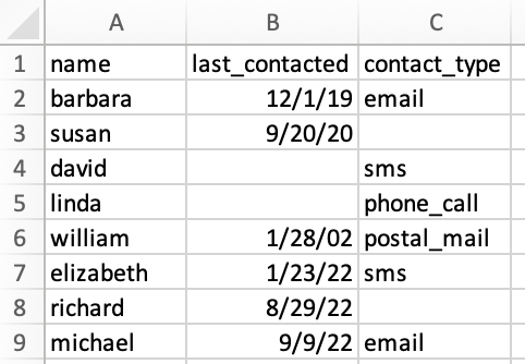
puis utilisera ce qui suit pour voir misc_part2:
SELECT * FROM misc_part2 ;
Résultats:
Nous pouvons considérer ces deux tableaux comme des données marketing sur la dernière fois que les clients ont été contactés et également sur la manière dont ils ont été contactés, par exemple par e-mail, appel téléphonique, etc. Il y a trois observations rien qu'en regardant les données :
Les deux tables ont les mêmes noms de colonne, il est donc peut-être possible de les combiner dans le cadre de notre exercice, que nous explorerons plus en détail sous UNION.
Certaines valeurs sont manquantes, ce qui n'était pas le cas dans les tables peopleet . salaryPar exemple, en regardant misc_part2, les cellules B5et B6sont vides. Il y a aussi des valeurs manquantes dans misc_part1. Nous discuterons de la gestion des nulls.
Les deux tables incluent une colonne de format de date, que nous n'avions pas dans les tables peopleet . salaryNous utiliserons ces valeurs pour certaines manipulations de date.
Comme la dernière fois, n'hésitez pas à prendre un instantané de ces deux tableaux pour votre référence, puis continuons avec le même format de questions et réponses pour couvrir de nouveaux concepts.
8.1. Opérateur UNION
Q13 : Je vois que les deux tables incluent les mêmes colonnes. Pouvez-vous les combiner en un seul tableau ? Triez les résultats par nom et identifiez également quelle ligne appartient à quelle table.
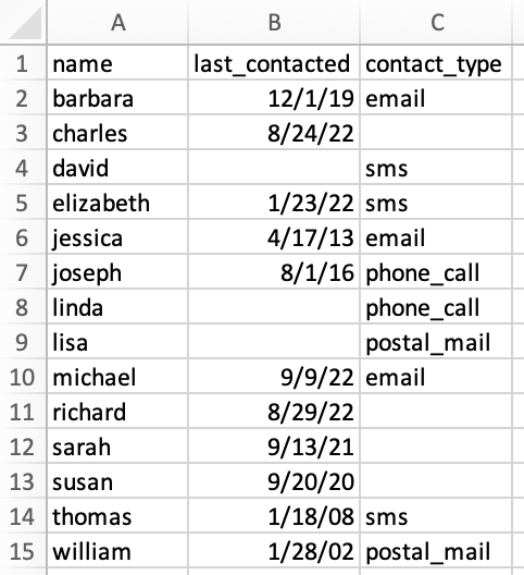
R13 : N'oubliez pas que nous avons commencé avec deux tableaux, chacun d'eux comprenant 8 lignes de données (à l'exclusion des en-têtes). Nous nous attendons donc à ce que le tableau combiné inclue 16 lignes de données (à l'exclusion des en-têtes).
Cela peut être fait UNION ALLen utilisant le format suivant :
SELECT *, 1 AS misc_table_number FROM misc_part1 UNION ALL SELECT *, 2 AS misc_table_number FROM misc_part2 ORDER BY nom ;
Résultats:
Les résultats incluent 16 lignes de données (à l'exclusion des en-têtes) comme prévu. Parlons de ce qui s'est passé.
UNION ALLL'opérateur place les données de chacune des requêtes et les empile les unes sur les autres. Quelques conditions doivent être remplies pour que cela fonctionne correctement :
Chaque SELECTélément de l' UNION ALLopérateur doit avoir le même nombre de colonnes. Par exemple, dans notre exercice chaque tableau comprend 4 colonnes.
Les colonnes correspondantes de chaque SELECTinstruction doivent avoir le même type de données. Par exemple, namedans les deux tables sont dans VARCHAR(30)le type de données, ou last_contacteddans les deux tables sont dans DATEle type de données.
Les colonnes de chacune des SELECTdéclarations doivent être dans le même ordre. En d'autres termes, l'ordre dans les deux tables de nos exemples de tables doit être name, last_contacted, contact_type, misc_table_number. Cette condition était également remplie dans notre exemple et c'est pourquoi nous avons pu utiliser UNION ALL.
Q14 : En examinant les résultats de la Q13, il semble que les deux tableaux contiennent les mêmes données pour davidet elizabeth. Pouvez-vous créer le même tableau mais n'inclure que des lignes uniques (c'est-à-dire dédoubler les résultats) ? Il n'est pas nécessaire d'indiquer à quelles lignes du tableau appartiennent.
A14 : Cela peut facilement être fait en utilisant UNION, au lieu de UNION ALL. En d'autres termes, UNIONne sélectionne que des valeurs distinctes, tandis que UNION ALLsélectionne toutes les valeurs. La requête est la suivante :
SELECT * FROM misc_part1 UNION SELECT * FROM misc_part2 ORDER BY nom ;
Résultats:
Comme prévu, les résultats n'incluent désormais que des lignes distinctes et le nombre total de lignes est désormais de 14 (hors en-têtes), au lieu de 16 au Q13.
8.2. Traitement nul
Q15 : Créez une table temporaire nommée combined_tablequi inclut des lignes distinctes des tables combinées (similaire à Q14). Lorsque last_contactedla valeur est manquante, entrez la valeur sous la forme 1901-01-01. Nous savons aussi que ce contact_typequi manque est phone_calldonc remplissez-les également.
A15 :
WITH combination_table as ( SELECT * FROM misc_part1 UNION SELECT * FROM misc_part2 ORDER BY name ) SELECT name, NVL(last_contacted, '1901-01-01') as last_contacted, COALESCE(contact_type, 'phone_call') AS contact_type FROM combination_table ;
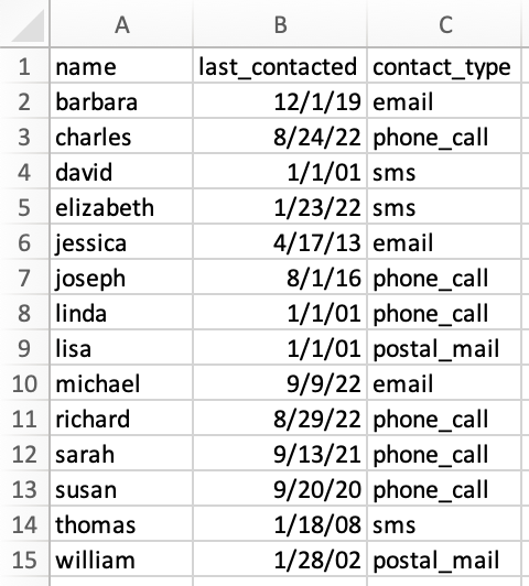
Résultats:
Les résultats sont conformes à nos attentes, alors parlons de ce qui s'est passé.
Il y a deux fonctions nulles que nous avons utilisées dans cet exercice et pour nos besoins, elles sont toutes les deux similaires. Ils renvoient tous les deux une valeur alternative lorsqu'une expression est NULL. Je voulais utiliser les deux pour les présenter tous les deux, mais vous pouvez choisir d'utiliser l'un ou l'autre. Regardons-les de plus près :
NVL(last_contacted, '1901-01-01') as last_contacted, COALESCE(contact_type, 'phone_call') AS contact_type
Le premier dit que lorsque vous rencontrez NULL dans la colonne last_contacted, remplacez-le par 1901-01-01. De même, le second dit que lorsque vous rencontrez NULL dans la colonne contact_type, remplacez-le par phone_call, comme indiqué dans la question.
Conseil de pro : selon l'environnement SQL, les instructions peuvent légèrement varier, mais les concepts restent les mêmes. Par exemple,COALESCE()est utilisé sur MySQL, SQL Server, Oracle et MS Access, alors qu'ilNVL()fonctionne principalement avec Oracle.
8.3. Gestion des dates
Q16 : En commençant par combined_table, créez des colonnes séparées pour l'année, le trimestre, le mois et la date de la dernière fois que les personnes ont été contactées, lorsqu'une telle date est disponible.
R16 : Examinons d'abord la structure et les résultats, puis discutons-en.
WITH combination_table as ( SELECT * FROM misc_part1 UNION SELECT * FROM misc_part2 ORDER BY name ) SELECT name, last_contacted, DATE_PART(year, last_contacted) AS year_contacted, DATE_PART(trimestre, last_contacted) AS quarter_contacted, DATE_PART(month, last_contacted) AS month_contacted, DATE_PART (jour, dernier_contacté) AS jour_contacté, type_contact FROM tableau_combiné WHERE dernier_contacté IS NOT NULL ;
Résultats:
Il y a deux nouveaux concepts à couvrir dans cet exercice. La première consiste à extraire une partie spécifique (par exemple, année, trimestre, mois ou jour) d'une date, qui peut être implémentée comme suit :
DATE_PART(year, last_contacted) AS year_contacted,
L'idée est simple. yearidentifie quelle partie de la date doit être extraite, puis elle est suivie du nom de la colonne où se trouve la date d'origine, qui est last_contacteddans cet exemple.
Le deuxième concept consiste à filtrer les lignes avec des valeurs NULL, ce qui a été accompli en utilisant ce qui suit :
WHERE last_contacted IS NOT NULL
Conseil de pro : dans SQL Server, au lieu deDATE_PART(), on utiliseDATEPART().
Section 3 — Aide-mémoire
J'ai inclus la feuille de triche que j'avais développée pour moi-même ici. Avant de commencer à l'utiliser, j'ai deux recommandations à ce sujet et sur d'autres aide-mémoire :
Dans la mesure du possible, créez votre propre feuille de triche au fil du temps, au lieu de vous fier à une feuille de triche préparée. Vous en apprendrez beaucoup plus lorsque vous le créerez et le mettrez à jour par vous-même, par rapport à celui qui est partagé avec vous.
Si vous n'avez pas le temps de créer votre propre feuille de triche, prenez une feuille de triche existante et personnalisez-la. Ce que je veux dire, c'est que commencez par la feuille de triche existante, mais ajoutez-y, révisez-la, modifiez-la et à un moment donné, elle deviendra "votre" feuille de triche et vous continuerez à apprendre en cours de route.
-- Introduction
SELECT column_1, column_2… [Returns entries per specified columns] SELECT * [Returns all entries] SELECT DISTINCT column_1, column_2… [Returns unique entries per specified columns] SELECT DISTINCT * [Returns all unique entries]
FROM schema_name.table_name [Specifies table to return entries from]
WHERE column_1 = ‘value’ [Specifies condition per column] May use =, >, <, >=, <=, <>
WHERE column_1 = ‘value’ AND column_2 = ‘value’ [Specifies both conditions must be met]
WHERE column_1 = ‘value’ OR column_2 = ‘value’ [Specifies one condition must be met]
WHERE column_1 = ‘value’ AND (column_2 = ‘value’ OR column_3 = ‘value’)
-- Aggregations
SUM(column_1) [Returns summation of column]
AVG(column_1) [Returns average of column]
MIN(column_1) [Returns minimum of column]
MAX(column_1) [Returns maximum of column]
COUNT(column_1) [Returns count of entries of column]
COUNT(DISTINCT column_1) [Returns unique count of entries of column]
Aggregations require a GROUP BY clause, i.e. GROUP BY 1, 2 or GROUP BY column_1, column_2 All non-aggregated columns are required to be in the GROUP BY clause
-- Null Handling
IS NULL [Evaluates if an entry is null]
IS NOT NULL [Evaluates if an entry is not null]
NVL(column_1, ‘alternative value’) [Replaces entry with an alternative value if found to be null]
NULLIF(column_1,’value’) [Replaces entry with null if entry meets value]
-- Aliases
column_1 AS ‘value’ [Renames column]
schema_name.table_name AS ‘value’ [Renames table]
-- Joins (added in From and then join on primary keys)
INNER JOIN schema_name.table_name ON table1.value1 = table2.value1 [Merges tables on matching values, contains only records with matching values found in both table 1 and table 2]
LEFT JOIN schema_name.table_name ON table1.value1 = table2.value1 [Merges tables on matching values, contains all records from table 1]
RIGHT JOIN schema_name.table_name ON table1.value1 = table2.value1 [Merges tables on matching values, contains all records from table 2]
FULL OUTER JOIN schema_name.table_name ON table1.value1 = table2.value1 [Merges tables on matching values, contains all records from both table 1 and table 2]
-- UNIONs
UNION [Merges two tables whose structures are the same, removes duplicative records] UNION ALL [Merges two tables whose structures are the same]
-- Miscellaneous
LIMIT x [Limits returned records to a specified number]
ORDER BY 1, 2 or ORDER BY column_1, column_2 [Orders returned records by specified columns]
LIKE ‘%value%’ [Used to find near matches when evaluating conditions]
IN (‘value 1’,’value 2’) [Used to find matches within a list of values when evaluating conditions]
BETWEEN ‘value 1’ AND ‘value 2’ [Used to find matches where an entry falls between two values when evaluating conditions] (inclusive)
HAVING [Used in place of WHERE for aggregate clauses] (WHERE filters before data is grouped. HAVING filters after data is grouped.)
CASE WHEN column1 = ‘value’ THEN ‘value’ ELSE ‘value’ END AS ‘value’ [Returns entries by evaluating when/then statements] CASE WHEN A THEN X WHEN B THEN Y WHEN C THEN Z ELSE W END
NOT [Used to limit to where a condition is not met]
-- Date Management
CURRENT_DATE [Returns current date]
TO_CHAR (column name, 'date format') [converts the date to a character string in a specified format] Date formats: 'YYYY/MM/DD' 'YYYY:MM:DD' 'Q' = Quarter number 'MM' = Month number 'Month' = Month name 'W' = Week of the month (1-5; first week starts on the first day of the month) 'WW' = Week number of year (1-53; first week starts on the first day of the year) 'Day' = Day name 'DDD' = Day of year (1-366) 'DD' = Day of month (1-31) 'D' = Day of week (1-7; Sunday is 1) 'YYYY/MM/DD HH24:MI:SS' = Year, month, day, hour, minutes and seconds
DATE_TRUNC ('datepart', column) [truncates a time stamps expression to a specified date part, such as hour, week or month] Datepart formats: 'year' = truncates to the first second of the first hour of the first day of the year 'quarter' = truncates to the first second/hour/day/quarter 'month' = truncates to the first second/hour/day/month 'week' = truncates to the first second/hour/day/week (Monday) 'day' = truncates to the first second/hour/day
This article explains a simple pure sine wave inverter circuit using Arduino, which could be upgraded to achieve any desired power output as per the user's preference
Contents
Circuit Operation
In the last article we learned how to generate sine wave pulse width modulation or SPWM though Arduino, we are going to use the same Arduino board to make the proposed simple pure sine wave inverter circuit.The design is actually extremely straightforward, as shown in the following figure.
You just have to program the arduino board with the SPWM code as explained in the previous article, and hook it up with some of the external devices.
Pin#8 and pin#9 generate the SPWMs alternately and switch the relevant mosfets with the same SPWM pattern.
The mosfst in turn induce the transformer with high current SPWM waveform using the battery power, causing the secondary of the trafo to generate an identical waveform but at the mains AC level.
The proposed Arduino inverter circuit could be upgraded to any preferred higher wattage level, simply by upgrading the mosfets and the trafo rating accordingly, alternatively you can also convert this into a full bridge or an H-bridge sine wave inverter
Powering the Arduino Board
In the diagram the Arduino board could be seen supplied from a 7812 IC circuit, this could be built by wiring a standard 7812 IC in the following manner. The IC will ensure that the input to the Arduino never exceeds the 12V mark, although this might not be absolutely critical, unless the battery is rated over 18V.
If you have any questions regarding the above SPWM inverter circuit using a programmed Arduino, please feel free to ask them through your valuable comments.
Waveform Images for Arduino SPWM
Image of SPWM waveform as obtained from the above Arduino inverter design (Tested and Submitted By Mr. Ainsworth Lynch)
UPDATE:
Using BJT Buffer Stage as Level Shifter
Since an Arduino board will produce a 5V output, it may not be an ideal value for driving mosfets directly.
Therefore an intermediate BJT level shifter stage may be required for raising the gate level to 12V so that the mosfets are able to operate correctly without causing unnecessary heating up of the devices,. The updated diagram (recommended) can be witnessed below:
The above design is the recommended one! (Just make sure to add the delay timer, as explained below!!)
Transformer = 9-0-9V/220V/120V current as per requirement.
Battery = 12V, Ah value as per requirement
Delay Effect
To ensure that the mosfet stages initiate with a delay during the Arduino booting or start up, you may modify left side BC547 transistors into delay ON stages, as shown below. This will safeguard the mosfets and prevent them from burning during power switch ON Arduino booting.
PLEASE TEST AND CONFIRM THE DELAY OUTPUT WITH AN LED AT THE COLLECTOR, BEFORE FINALIZING THE INVERTER. FOR INCREASING THE DELAY YOU CAN INCREASE THE 10K VALUE TO 100K
Adding an Automatic Voltage Regulator
Just like any other inverter the output from this design can rise to unsafe limits when the battery is fully charged.
The BC547 collectors should be connected to the bases of the left side BC547 pair, which are connected to the Arduino via 10K resistors.
For an isolated version of voltage correction circuit we can modify the above circuit with a transformer, as shown below:
Make sure to join the negative line with the battery negative
How to Setup
To set up the automatic voltage correction circuit, feed a stable 230V or 110V as per your inverter specs to the input side of the circuit.
Next, adjust the 10k preset carefully such that the red LEDs just light up. That's all, seal the preset and connect the circuit with the above Arduino board for implementing the intended automatic output voltage regulation.
Using CMOS Buffer
Another design for the above Arduino sinewave inverter circuit can be seen below, the CMOS IC is used as an aided buffer for the BJT stage
Important:
In order to avoid an accidental switch ON prior to Arduino booting, a simple delay ON timer circuit may be included in the above design, as shown below:
I am an electronic engineer (dipIETE ), hobbyist, inventor, schematic/PCB designer, manufacturer. I am also the founder of the website: https://www.homemade-circuits.com/, where I love sharing my innovative circuit ideas and tutorials. If you have any circuit related query, you may interact through comments, I'll be most happy to help!
Have Questions? Please Comment below to Solve your Queries! Comments must be Related to the above Topic!!
Subscribe
508 COMMENTS
Newest
Ajit Mohanty
2 days ago
very interesting. can we convert DC to AC 11w tube using hybrid transformer? expecting your valuable guidance.
Hi Swagatam I am Designing the H bridge converter, I required Sinusoidal at high frequency (3kHz). Can you guide me on How should I change the Arduino code to obtain High Frequency at Output? Regards
Hi Leo, you can probably try the following circuit for the H bridge design, but make sure the battery and transformer are 12V rated..webp Changing the code can be plenty of hard work and a lot of thinking. Basically you will have to replace each of the microsecond delays with smaller delays such that they together add up to produce 3000 Hz for each channel.
Bob Gardner
3 months ago
Hello Swagatam. You have great circuits and great explanations to teach folks about the circuits. Here’s my idea: 55 gal blue drum full of 400 pounds of water is my gravity battery. Pull it up to some height with a block and tackle. My goal is to run a 5000 btu ac for 1 hour. 5000btuas/3412btusper kw is about 1400 watts, and running this contraption would give some cool air for an hour. Then make someone else crank the drum back to to run it again. At first I looked into a 3phase PMA alternator that puts out 12V 3phase… Read more »
If you are looking for a circuit to limit the speed and the voltage output of an alternator, then yes that can be done through a simple shunt regulator circuit. Is the alternator a 3 phase alternator or a single phase alternator?
Hello Swagatam. I wish to thank you for all the circuits you make available for free on your site. They are very educational to a amateur radio operator like me. My call is KE4WCE. My question is where in the code for the Arduino Pure Sine Wave Inverter Circuit would I need to change from 50Hz (cycles) to 60Hz and replace it with what number. Or if you don’t mind me asking the math formula and a example so I may able to do it myself. Thank You 73’s
Thank you very much Amos, In the Arduino code explained above we have used the total delay on each channel as 10 ms, since each 50 Hz AC half cycle requires 10ms to complete. For a 60 Hz cycle the completion time of half cycle becomes 12 ms. So you will have to adjust the microsecond time (in brackets) on each channel of the code in such a way that it produces a delay of 12 ms or 12000 microseconds.
HI, I Build the first most simple’s project on the page. After programming my arduino I founded that my irf540 is heating up and when i checked the frequency on my arduino ouput it was around 500 hz . I am most certain thats why the mosfets heat up. I cannot see what i am doing wrong. Advise please
MOSFETs can work with frequencies up to MHz and GHz, so frequency can never be a problem, I have tested the design thoroughly and had no such problems. My MOSFETs also heated up a a little but it was because of the 100 watt load at the output of the transformer. If your MOSFETs are heating up due to an output load then it is normal, simply put a heatsink on it.
VIvek Jadhav
3 months ago
And one more thing…. instead of using high voltage capacitors at transformer output for waveform smoothing. can we use low voltage capacitors at the transformer input??? voltage and power handling will be easier… what say??
I don’t think that might be possible, because at the input side everything is PWM based and digital which cannot be transformed into an analogue sine wave….the transformation may be possible only at the output side of the transformer.
VIvek Jadhav
3 months ago
Hiii Swagatam, The delay circuit is introduced as a safety. But What I say is instead of introducing a circuit why dont we use aurduino digital output signal to switch the DC supply to inverter circuit. mainly for three reasons, 1) Human error is eliminated. 2) circuit is simplified 3) Delay circuit malfunction hazard is also eliminated. Whats your say in this??
Thanks Vivek, My Arduino knowledge is not good, so I won’t be able to suggest on this modification. If you think this is something feasible then surely it can be implemented and tried in this design.
Christiaan Esterhuyse
4 months ago
Best Swagatam
I may be understanding the circuit diagram wrong but I simulated the circuit and it does not seem to work. I don’t understand how the positive terminal can be connected directly to the base of the mosfet. What is the reason for the BJT level shifters? Also a positive voltage is applied again directly (resistor in series… so voltage division?) to the bjt. I would like to build this circuit but cannot seem to understand its working principle. Would it be possible to communicate by email for me to better understand the circuit please?
Christiaan, level shifters are necessary to enable the mosfets gates to get 12V supply so that they can conduct optimally. If we connect the mosfets directly with the Arduino, the gates will be be able to get only 5V which may not be sufficient for the mosfets to switch ON perfectly. The first BC547 inverts the Arduino PWM so it cannot be directly used with the mosfets otherwise the mosfets gates would be switched with inverse PWM signals. The second BC547 corrects this issue and makes the PWM same as the Arduino output, but at 12V level The circuit is… Read more »
Thank you for the response. That makes sense but wont the voltage to the mosfet be 13.3V since this is more the operating voltage of a 12V battery? Is this still a suitable value? Then lastly do you have a inverter circuit that does not use a transformer but still steps up from 12V to 230V? Sincerely Christiaan
Most mosfet gates are designed to work with upto 20V, so 13V is quite OK. Making an 12V to 230V inverter without a transformer is almost impossible, as far as I know.
Lalawmpuia, where do you think the feedback can be connected with the Arduino? It will require special coding for that. Connecting the feedback to MOSFET gates is an universal option which can configured easily without any coding by anybody and with any inverter.
Sir can you please explain how the BC547 collector is connected to the base/gate of the BJT/Mosfet . Since I have a hard time understanding that . Since the emmiter side is connected to ground and does that simply pull down ?
The BC547 collector will pull down the mosfet gate while it is ON, and when it is OFF the mosfet gate will get the switching voltage through the 1K resistor.
How does the feedback works? since the feedback ( bc547) emmiter is connected to the base of the bc547( arduino output ) will it just pull down from bc547 base to ground . Please explain the worling of this feedback . Also I tried your Circuit and code as well but I have burn out 10 mosfet ( 5 times irfz44n and 5 times irf3205 ) in just under 10 seconds . It was too hot to even touch .
When the input voltage to the op amp circuit exceeds the set limit the op amp output and the BC547 conduct and grounds the Arduino BC547 bases causing the mosfets to shut off. As soon as the mosfets are turned off the voltage begins to drop which reverts the opamp output causing the mosfets to switch ON again, and this process continues which keeps the output voltage within the desired range. Your mosfets may be burning due to some fault in your design, or may be the mosfets are not good quality. You can in the video the circuit works… Read more »
Hello sir , I have a question about the transformer , if I use a 6-0-6 transformer rated at 3A , at ideal mode , what will be the rated watt of the output ? Since 3A is the highest rated transformer I can buy from our state .
Hello sir , how are you ? I have one question regarding the feedback , my circuit is exactly same as your circuit , and the transformer I used is from an old ups , and the question is , the output Voltage decrease to 140V from 210V when connected a load . Will the feedback you posted work in this situation to give 220V constant even when connected to a load ( 60W incandescent lamb) ?
Hello Fanai, no, the feedback cannot boost a low voltage happening due to over load or low wattage transformer/battery, it can only prevent an over voltage. To correct the voltage drop you must ensure that the transformer, battery and the mosfets are appropriately rated as per the load requirement.
mike webb
8 months ago
k. well the solution i have now will have to do till i have more time. seems the best way forward will be to build an inverter that doesnt have over voltage protection. when i have time i’ll pull the transformer out of the old inverter, check it to make sure it meets the specs of the Arduino. i’ll also grab the heat sinks for the mosfets. then i’ll have another 1000 questions for you. thank you for your help.
this may be off topic, i’m looking at building this inverter but perhaps its better to tell you what my problem is first because you may have a better solution. i have a 300 watt inverter thats doing just fine. but its connected to lithium ion batterys instead of lead acid. the ion batterys are 4p so top voltage is 16.4. the inverter has i high voltage cut off at 15.5. i’m working around the problem by placing a buck inverter between the batterys and the inverter, the buck inverter is set to output at 14.9 volts. this works but… Read more »
Using a buck converter between the battery and the inverter can be indeed quite wasteful, but unfortunately there’s no other more efficient way than a buck converter, except if one Li-Ion cell is reduced, and a 3S combination is used with a 12.6V output supply. The transformer winding rating must match the PWM average of the Arduino in the above explained concept. The average voltage at the collector of the first BC547 transistor will be the value that must match the half winding specs of the transformer. So definitely you can salvage the transformer from your 3000 watt inverter but… Read more »
Johnny
1 year ago
Hi Mr i have built a small circuit using Bc547 & Bc557 as BJT Buffer stage to drive the Mosfets (i’m using IRFZ46) when i check the ouput of the buffer stage connected to Arduino uploaded with Spwm Code on DSO138 oscilloscope the output is same as the pattern of the wave in the picture on the page But on the Drain of the Mosfet its square wave Why? My circuit using readymade oscillator SG3524 is working fine But using the Arduino the output is connected to lamp & is flashing any idea? thanks for ur Help
I need another circuit which i didnt know how to contact the page a small Solid state relay using mosfets which have Com positive or negative 12V NC NO so i can select which source to use power of 2 12v dc inputs & 1 output \]
That is actually not possible. The ON/OFF switching of the drain is dependent on the ON/OFF switching of its gate, and has to be exactly similar. Not sure why it is not happening for your mosfet…
Alan K Gilman
1 year ago
It’s interesting how people solve a problem based on their background. You designed a delay circuit to insure there are no shoot-through conditions at startup. Being a software engineer, I would have done this in software by driving the relay with transistor and an output from the Arduino :-). Great article, thanks for publishing!
Hi Nimel, the pin8 and pin9 go to the first BC547 via 10k, this BC547 base is configured with the delay timer network, so it is the pin8 nd pin9 which go to the delay network
Partha Gorai
1 year ago
Sir, can you please share the transformar specification, required for this project. Thanks.
Partha, the transformer voltage can be 6-0-6V for a 12V battery. Transformer current will depend on the load wattage. If the load wattage is 200 watt then dividing this by 6 becomes 33 amps and so on.
Patrick
1 year ago
Hello Sir, Thanks for the article,i would love to know more on the programming aspect.Please can you explain in detail how the avr side of the above circuit works to protect the circuit,like when the LED lights up,what does it mean,and can i implement it on all other inverter circuit?
Thank you for liking the post! Yes you an change the frequency to any desired value, simply by altering the “microsecond” values in the code. As you can see, the above applications works with 50 Hz frequency, therefore the microsecond delays in the code across both the channels are adjusted accordingly to a 20 ms value. For 1kHz, this total delay for the entire code will need to be adjusted to 1 ms.
Hi, If you are going to use 1kHz, then you will probably need to design or obtain a transformer suitable for the job. The 50/60Hz transformers used here will not provide the performance at 1 kHz.
The impedance of the transformer is lower at 50/60Hz than at 1 kHz.
dead time already introduced at the end of the codes for each channel
digitalWrite(8, LOW); //……
digitalWrite(9, LOW); } //————————————-//
Jayvardhan pandit
1 year ago
Thanks for quick reply on my previous comments. I want to know one more thing how output frequency calculated. For some spacial applicatoin i want to lower the frequency about 10Hz to 15Hz. Please help.
It will depend on the specific oscillator circuit, and the RC parts used in the oscillator. The frequency can be changed by changing the RC values of the oscillator.
Yes, for the above Arduino, the frequency is dependent on the delay (microsecond) set for each of the PWM blocks. You can modify them accordingly to ensure the waveform delay coincides with the frequency timing or the Hz rate
Jaywardhan
2 years ago
Hi, Nice projects is this, I want to make this same project with 110V DC source, can i replace 12V DC source with 110V? Second thing in place of saperate Power On delay circuit, we can also use Arduino itself for the same.
[[{"text":"Vous allez répondre à un QCM sur la partie 1 du programme de NSI : Encodage des données.
Consignes :
- 1 seul moniteur d'allumé;
- 1 seul onglet ouvert sur sciencesappliquees.com dans le navigateur chrome;
- Aucun autre logiciel doit être exécuté pendant le test.
Si vous enfreignez une de ces consignes, vous aurez 0 avec 2 heures de colles pour tentative de triche!
","title":"","posi":0}],[{"text":"Quel est un avantage du codage UTF8 par rapport au codage ASCII ?","theme":"A","nume":"1","sujet":3,"annee":2020},{"radio":[{"label":" il permet de coder un caractère sur un octet au lieu de deux"},{"label":" il permet de coder les majuscules"},{"label":" il permet de coder tous les caractères","sol":true},{"label":" il permet de coder différentes polices de caractères"}]}],[{"text":"On considère les codes ASCII en écriture hexadécimale (en base 16). Le code ASCII de la lettre A est 0x41, celui de la lettre B est 0x42, celui de la lettre C est 0x43, etc. Quel est le code ASCII, en hexadécimal, de la lettre X (c'est la 24e lettre de l'alphabet usuel). ","theme":"A","nume":"2","sujet":3,"annee":2020},{"radio":[{"label":" 0x58","sol":true},{"label":" 0x64"},{"label":" 0x7A"},{"label":" 0x88"}]}],[{"text":"Quelle est la représentation en binaire de l'entier 65 sur un octet ?","theme":"A","nume":"3","sujet":3,"annee":2020,"posi":3},{"radio":[{"label":" 0101 0000"},{"label":" 1100 0101"},{"label":" 0100 0001","sol":true},{"label":" 0000 1100"}]}],[{"text":"Le codage d’une couleur se fait à l'aide de trois nombres compris chacun, en écriture décimale, entre 0 et 255 (code RVB). La couleur « vert impérial » est codée, en écriture décimale, par (0, 86, 27). Le codage hexadécimal correspondant est :","theme":"A","nume":"4","sujet":3,"annee":2020},{"radio":[{"label":" (0, 134, 39)"},{"label":" (0, 134, 1B)"},{"label":" (0, 56, 1B)","sol":true},{"label":" (0, 56, 39)"}]}],[{"text":"Quelle est l’écriture hexadécimale de l’entier dont la représentation en binaire non signé est 1100 0111 ? ","theme":"A","nume":"5","sujet":3,"annee":2020},{"radio":[{"label":" BB"},{"label":" C7","sol":true},{"label":" CB"},{"label":" 7610"}]}],[{"text":"Quel est le nombre maximal de bits du produit de deux entiers positifs codés sur 8 bits ?","theme":"A","nume":"6","sujet":3,"annee":2020},{"radio":[{"label":"8 "},{"label":" 16 ","sol":true},{"label":" 32 "},{"label":" 64"}]}],[{"text":"Un nombre entier signé est codé en complément à deux sur 8 bits par : 0111 0101. Que peut-on dire ?","theme":"A","nume":"1","sujet":4,"annee":2020},{"radio":[{"label":" c'est un nombre positif","sol":true},{"label":" c'est un nombre négatif"},{"label":" c'est un nombre pair"},{"label":" 7 bits auraient suffi à représenter cet entier signé en complément à deux"}]}],[{"text":"Comment s'écrit en base 16 (en hexadécimal) le nombre dont l'écriture binaire est 0011 1100 ? ","theme":"A","nume":"2","sujet":4,"annee":2020},{"radio":[{"label":" 1D"},{"label":"3C","sol":true},{"label":" 3C "},{"label":" 3E"}]}],[{"text":"On considère les nombres dont l'écriture en base 16 (en hexadécimal) sont de la forme suivante : un 1 suivi de 0 en nombre quelconque, comme 1, 10, 100, 1000 etc. Tous ces nombres sont exactement :","theme":"A","nume":"3","sujet":4,"annee":2020},{"radio":[{"label":" les puissances de 2","sol":true},{"label":" les puissances de 8"},{"label":" les puissances de 10"},{"label":" les puissances de 16","sol":true}]}],[{"text":"Quelle est la représentation hexadécimale de l'entier qui s'écrit 106 en base 10 ? ","theme":"A","nume":"4","sujet":4,"annee":2020},{"radio":[{"label":" 6A","sol":true},{"label":" A6"},{"label":" 64 "},{"label":" 46"}]}],[{"text":"Quel est le résultat de l'addition binaire 0010 0110 + 1000 1110 ? ","theme":"A","nume":"5","sujet":4,"annee":2020},{"radio":[{"label":" 1010 1110"},{"label":" 0000 0110"},{"label":" 1011 0100","sol":true},{"label":" 0101 0001"}]}],[{"text":"Combien de bits doit-on utiliser au minimum pour représenter en base 2 le nombre entier 72 ?","theme":"A","nume":"6","sujet":4,"annee":2020},{"radio":[{"label":"2 "},{"label":"6 "},{"label":"7 ","sol":true},{"label":"8","sol":false}]}],[{"text":"Le résultat de la soustraction en binaire 101001 - 101 est égal au nombre binaire :","theme":"A","nume":"1","sujet":5,"annee":2020},{"radio":[{"label":" 100000"},{"label":" 101110"},{"label":" 100100","sol":true},{"label":" 100110"}]}],[{"text":"Quelle est l'écriture décimale de l'entier positif dont l'écriture hexadécimale (en base 16) est 3E ? ","theme":"A","nume":"2","sujet":5,"annee":2020},{"radio":[{"label":" 18"},{"label":" 45"},{"label":" 62","sol":true},{"label":" 315"}]}],[{"text":"Quel est l'entier relatif codé en complément à 2 sur un octet par le code 1111 1111 ? ","theme":"A","nume":"3","sujet":5,"annee":2020},{"radio":[{"label":" – 128"},{"label":" – 127","sol":false},{"label":"–1 ","sol":true},{"label":" 255"}]}],[{"text":"Quelle est, en écriture décimale, la somme d'entiers dont l'écriture en base 16 (hexadécimale) est 2A + 3 ? ","theme":"A","nume":"4","sujet":5,"annee":2020},{"radio":[{"label":" 22"},{"label":" 31"},{"label":" 49 "},{"label":" 45","sol":true}]}],[{"text":"Laquelle de ces affirmations concernant le codage UTF-8 des caractères est vraie ?","theme":"A","nume":"6","sujet":5,"annee":2020},{"radio":[{"label":" le codage UTF-8 est sur 7 bits"},{"label":" le codage UTF-8 est sur 8 bits"},{"label":" le codage UTF-8 est sur 1 à 4 octets","sol":true},{"label":" le codage UTF-8 est sur 8 octets"}]}],[{"text":"Soit 𝑛 l'entier dont la représentation binaire en complément à deux codée sur 8 bits est 0110 1110. Quelle est la représentation binaire de −𝑛 ?","theme":"A","nume":"1","sujet":6,"annee":2020},{"radio":[{"label":" 0001 0001"},{"label":" 0001 0010"},{"label":" 1001 0001","sol":false},{"label":" 1001 0010","sol":true}]}],[{"text":"À quoi sert le codage en complément à 2 ?","theme":"A","nume":"3","sujet":6,"annee":2020},{"radio":[{"label":" à inverser un nombre binaire"},{"label":" à coder des nombres entiers négatifs en binaire","sol":true},{"label":" à convertir un nombre en hexadécimal"},{"label":" à multiplier par 2 un nombre en binaire"}]}],[{"text":"Quel est le plus grand entier positif que l'on peut coder sur un mot de 16 bits ?","theme":"A","nume":"1","sujet":7,"annee":2020},{"radio":[{"label":" 215−1=32767"},{"label":" 215 = 32768"},{"label":" 216−1=65535","sol":true},{"label":" 216 = 65536"}]}],[{"text":"Combien de bits sont nécessaires pour représenter 15 en binaire ?","theme":"A","nume":"2","sujet":7,"annee":2020},{"radio":[{"label":"2 "},{"label":"3 "},{"label":"4 ","sol":true},{"label":"5"}]}],[{"text":"Deux entiers positifs ont pour écriture en base 16 : A6 et 84. Quelle est l'écriture en base 16 de leur somme ?","theme":"A","nume":"4","sujet":7,"annee":2020},{"radio":[{"label":" 1811"},{"label":" 12B"},{"label":" 12A","sol":true},{"label":" A784"}]}],[{"text":"Quelle est la valeur de l’entier négatif –42 codé en complément à deux sur un octet (8 bits) ?","theme":"A","nume":"6","sujet":7,"annee":2020},{"radio":[{"label":" –0010 1010"},{"label":" 0010 1010"},{"label":" 1101 0101"},{"label":" 1101 0110","sol":true}]}],[{"text":"Parmi les caractères ci-dessous, lequel ne fait pas partie du code ASCII ?","theme":"A","nume":"2","sujet":8,"annee":2020},{"radio":[{"label":"a "},{"label":"B "},{"label":"@ "},{"label":"é","sol":true}]}],[{"text":"Quelle est l'écriture en hexadécimal (base 16) du nombre entier positif qui s'écrit 1111 1101 en base 2 ? ","theme":"A","nume":"3","sujet":8,"annee":2020},{"radio":[{"label":" DE"},{"label":"FD","sol":true},{"label":" EDF"},{"label":" FEFD"}]}],[{"text":"Que peut-on dire du programme Python suivant de calcul sur les nombres flottants ? x = 1.0 while x != 0.0: x = x - 0.1","theme":"A","nume":"1","sujet":9,"annee":2020},{"radio":[{"label":" l'exécution peut ne pas s'arrêter, si la variable x n'est jamais exactement égale à 0.0","sol":true},{"label":" à la fin de l'exécution, x vaut – 0.00001"},{"label":" à la fin de l'exécution, x vaut 0.00001"},{"label":" l'exécution s'arrête sur une erreur FloatingPointError"}]}],[{"text":"Combien de bits faut-il au minimum pour coder le nombre décimal 4085 ?","theme":"A","nume":"1","sujet":10,"annee":2020},{"radio":[{"label":"4"},{"label":" 12","sol":true},{"label":" 2042"},{"label":" 2043"}]}],[{"text":"Quelle est la représentation binaire du nombre entier 175 ?","theme":"A","nume":"3","sujet":10,"annee":2020},{"radio":[{"label":" 1010 1111","sol":true},{"label":" 1011 0101"},{"label":" 1011 0100"},{"label":" 1011 1101"}]}],[{"text":"Quelle est l'écriture décimale du nombre qui s'écrit 11,0101 en binaire ?","theme":"A","nume":"5","sujet":10,"annee":2020},{"radio":[{"label":"3"},{"label":" 3,0101"},{"label":" 3,05"},{"label":" 3,3125","sol":true}]}],[{"text":"Quelle est l'écriture binaire sur 8 bits en complément à deux de l'entier négatif –108 ?","theme":"A","nume":"6","sujet":10,"annee":2020},{"radio":[{"label":" 1000 1000"},{"label":" 0110 1100"},{"label":" 1001 0100","sol":true},{"label":" 1110 1100"}]}],[{"text":"Combien de nombres entiers positifs peut-on coder en binaire sur 4 bits ?","theme":"A","nume":"3","sujet":11,"annee":2020},{"radio":[{"label":"4"},{"label":" 16","sol":true},{"label":" 64"},{"label":" 256"}]}],[{"text":"La couleur « bleu roi » a pour code RGB (65,105,225), sa représentation en hexadécimal est :","theme":"A","nume":"4","sujet":11,"annee":2020},{"radio":[{"label":" #2852C2"},{"label":" #4169E1","sol":true},{"label":" #33A5C61"},{"label":" #C3T622"}]}],[{"text":"Quel est le nombre minimum de bits qui permet de représenter les 7 couleurs de l'arc-en-ciel ?","theme":"A","nume":"5","sujet":11,"annee":2020},{"radio":[{"label":"2 "},{"label":"3 ","sol":true},{"label":"4 "},{"label":"5"}]}],[{"text":"Quelle est l’écriture décimale de l’entier dont la représentation en binaire non signé est 0001 0111 ? ","theme":"A","nume":"1","sujet":12,"annee":2020},{"radio":[{"label":" 15"},{"label":" 23","sol":true},{"label":" 111"},{"label":" 420"}]}],[{"text":"Combien de bits sont nécessaires pour écrire le nombre entier 16 en base 2?","theme":"A","nume":"2","sujet":12,"annee":2020},{"radio":[{"label":"4 "},{"label":"5 ","sol":true},{"label":"6 "},{"label":"7"}]}],[{"text":"Quelle est l'écriture décimale de l'entier positif dont la représentation binaire est 1101 0101 ? ","theme":"A","nume":"3","sujet":12,"annee":2020},{"radio":[{"label":" 135"},{"label":" 213","sol":true},{"label":" 231"},{"label":"42"}]}],[{"text":"Combien de valeurs entières positives ou nulles un octet peut-il représenter ?","theme":"A","nume":"4","sujet":12,"annee":2020},{"radio":[{"label":"2 "},{"label":"8"},{"label":" 16 "},{"label":" 256","sol":true}]}],[{"text":"L'entier positif 255 se représente en hexadécimal (base 16) par :","theme":"A","nume":"3","sujet":13,"annee":2020},{"radio":[{"label":" 99 "},{"label":" AA "},{"label":" CC "},{"label":" FF","sol":true}]}],[{"text":"Quelle est l'écriture décimale de l'entier qui s'écrit 1011 en binaire ?","theme":"A","nume":"2","sujet":14,"annee":2020},{"radio":[{"label":"5 "},{"label":" 11","sol":true},{"label":" 20 "},{"label":" 22"}]}],[{"text":"Quelle est la représentation hexadécimale de l'entier dont la représentation binaire s'écrit : 0100 1001 1101 0011 ?","theme":"A","nume":"1","sujet":15,"annee":2020},{"radio":[{"label":" 18899"},{"label":" 3D94"},{"label":" 49D3","sol":true},{"label":" 93A3"}]}]]
En poursuivant votre navigation sur mon site,
vous acceptez l’utilisation des Cookies et autres traceurs
pour réaliser des statistiques de visites et enregistrer
sur votre machine vos activités pédagogiques.En savoir plus.
Have Questions? Please Comment below to Solve your Queries! Comments must be Related to the above Topic!!
very interesting. can we convert DC to AC 11w tube using hybrid transformer?
expecting your valuable guidance.
Yes that’s possible. Yu can try the following circuit:
https://www.homemade-circuits.com/electronic-ballast-circuit-for-uv-germicidal-lamps/
Hi Swagatam
I am Designing the H bridge converter, I required Sinusoidal at high frequency (3kHz). Can you guide me on How should I change the Arduino code to obtain High Frequency at Output?
Regards
Hi Leo,
.webp
you can probably try the following circuit for the H bridge design, but make sure the battery and transformer are 12V rated.
Changing the code can be plenty of hard work and a lot of thinking. Basically you will have to replace each of the microsecond delays with smaller delays such that they together add up to produce 3000 Hz for each channel.
Hello Swagatam. You have great circuits and great explanations to teach folks about the circuits. Here’s my idea: 55 gal blue drum full of 400 pounds of water is my gravity battery. Pull it up to some height with a block and tackle. My goal is to run a 5000 btu ac for 1 hour. 5000btuas/3412btusper kw is about 1400 watts, and running this contraption would give some cool air for an hour. Then make someone else crank the drum back to to run it again. At first I looked into a 3phase PMA alternator that puts out 12V 3phase… Read more »
Thanks Bob! Your concept looks interesting.
If you are looking for a circuit to limit the speed and the voltage output of an alternator, then yes that can be done through a simple shunt regulator circuit. Is the alternator a 3 phase alternator or a single phase alternator?
Hello Swagatam.
I wish to thank you for all the circuits you make available for free on your site. They are very educational to a amateur radio operator like me. My call is KE4WCE.
My question is where in the code for the Arduino Pure Sine Wave Inverter Circuit would I need to change from 50Hz (cycles) to 60Hz and replace it with what number.
Or if you don’t mind me asking the math formula and a example so I may able to do it myself.
Thank You 73’s
Thank you very much Amos,
In the Arduino code explained above we have used the total delay on each channel as 10 ms, since each 50 Hz AC half cycle requires 10ms to complete. For a 60 Hz cycle the completion time of half cycle becomes 12 ms. So you will have to adjust the microsecond time (in brackets) on each channel of the code in such a way that it produces a delay of 12 ms or 12000 microseconds.
Thank you For the fast reply. I am going to have a go at it and see if I can duplicate your circuit. Again Thank you for your time and patience.
73’s
I am glad to help!
HI,
I Build the first most simple’s project on the page. After programming my arduino I founded that my irf540 is heating up and when i checked the frequency on my arduino ouput it was around 500 hz . I am most certain thats why the mosfets heat up. I cannot see what i am doing wrong. Advise please
Regards
Peter
MOSFETs can work with frequencies up to MHz and GHz, so frequency can never be a problem, I have tested the design thoroughly and had no such problems. My MOSFETs also heated up a a little but it was because of the 100 watt load at the output of the transformer. If your MOSFETs are heating up due to an output load then it is normal, simply put a heatsink on it.
And one more thing…. instead of using high voltage capacitors at transformer output for waveform smoothing. can we use low voltage capacitors at the transformer input??? voltage and power handling will be easier… what say??
I don’t think that might be possible, because at the input side everything is PWM based and digital which cannot be transformed into an analogue sine wave….the transformation may be possible only at the output side of the transformer.
Hiii Swagatam, The delay circuit is introduced as a safety. But What I say is instead of introducing a circuit why dont we use aurduino digital output signal to switch the DC supply to inverter circuit. mainly for three reasons, 1) Human error is eliminated. 2) circuit is simplified 3) Delay circuit malfunction hazard is also eliminated. Whats your say in this??
Thanks Vivek,
My Arduino knowledge is not good, so I won’t be able to suggest on this modification. If you think this is something feasible then surely it can be implemented and tried in this design.
Best Swagatam
I may be understanding the circuit diagram wrong but I simulated the circuit and it does not seem to work.
I don’t understand how the positive terminal can be connected directly to the base of the mosfet. What is the reason for the BJT level shifters? Also a positive voltage is applied again directly (resistor in series… so voltage division?) to the bjt. I would like to build this circuit but cannot seem to understand its working principle.
Would it be possible to communicate by email for me to better understand the circuit please?
Kindest Regards Christiaan
Christiaan, level shifters are necessary to enable the mosfets gates to get 12V supply so that they can conduct optimally. If we connect the mosfets directly with the Arduino, the gates will be be able to get only 5V which may not be sufficient for the mosfets to switch ON perfectly. The first BC547 inverts the Arduino PWM so it cannot be directly used with the mosfets otherwise the mosfets gates would be switched with inverse PWM signals. The second BC547 corrects this issue and makes the PWM same as the Arduino output, but at 12V level The circuit is… Read more »
Thank you for the response.
That makes sense but wont the voltage to the mosfet be 13.3V since this is more the operating voltage of a 12V battery? Is this still a suitable value?
Then lastly do you have a inverter circuit that does not use a transformer but still steps up from 12V to 230V?
Sincerely Christiaan
Most mosfet gates are designed to work with upto 20V, so 13V is quite OK.
Making an 12V to 230V inverter without a transformer is almost impossible, as far as I know.
Thanks for the replies Swagatam.
This is definitely one of the only sites where you get replies.
What is the wattage of this inberter?
It’s my pleasure Tiaan.
Hello
Can you show the charging circuit?
All the best
J K BARIK
Sure, you can get the desired battery charger circuit from these two articles:
Lead Acid Battery Charger Circuits
Op amp Battery Charger Circuit with Auto Cut Off
Hello sir , can you please tell me how the feedback circuit works and why you connect them in the gate of the Mosfet but not in the arduino .
Lalawmpuia, where do you think the feedback can be connected with the Arduino? It will require special coding for that. Connecting the feedback to MOSFET gates is an universal option which can configured easily without any coding by anybody and with any inverter.
Sir can you please explain how the BC547 collector is connected to the base/gate of the BJT/Mosfet . Since I have a hard time understanding that . Since the emmiter side is connected to ground and does that simply pull down ?
The BC547 collector will pull down the mosfet gate while it is ON, and when it is OFF the mosfet gate will get the switching voltage through the 1K resistor.
How does the feedback works? since the feedback ( bc547) emmiter is connected to the base of the bc547( arduino output ) will it just pull down from bc547 base to ground . Please explain the worling of this feedback . Also I tried your Circuit and code as well but I have burn out 10 mosfet ( 5 times irfz44n and 5 times irf3205 ) in just under 10 seconds . It was too hot to even touch .
When the input voltage to the op amp circuit exceeds the set limit the op amp output and the BC547 conduct and grounds the Arduino BC547 bases causing the mosfets to shut off. As soon as the mosfets are turned off the voltage begins to drop which reverts the opamp output causing the mosfets to switch ON again, and this process continues which keeps the output voltage within the desired range. Your mosfets may be burning due to some fault in your design, or may be the mosfets are not good quality. You can in the video the circuit works… Read more »
Thank you so much .
Hello sir , I have a question about the transformer , if I use a 6-0-6 transformer rated at 3A , at ideal mode , what will be the rated watt of the output ? Since 3A is the highest rated transformer I can buy from our state .
Hello Fanai, it will be 6 x 3 = 18 watts for each half cycle of AC output, that means for one full AC cycle it can be around 36 watts
Hello sir , how are you ?
I have one question regarding the feedback , my circuit is exactly same as your circuit , and the transformer I used is from an old ups , and the question is , the output Voltage decrease to 140V from 210V when connected a load . Will the feedback you posted work in this situation to give 220V constant even when connected to a load ( 60W incandescent lamb) ?
Hello Fanai, no, the feedback cannot boost a low voltage happening due to over load or low wattage transformer/battery, it can only prevent an over voltage. To correct the voltage drop you must ensure that the transformer, battery and the mosfets are appropriately rated as per the load requirement.
k. well the solution i have now will have to do till i have more time. seems the best way forward will be to build an inverter that doesnt have over voltage protection. when i have time i’ll pull the transformer out of the old inverter, check it to make sure it meets the specs of the Arduino. i’ll also grab the heat sinks for the mosfets. then i’ll have another 1000 questions for you. thank you for your help.
Sure, no problem, all the best to you!
this may be off topic, i’m looking at building this inverter but perhaps its better to tell you what my problem is first because you may have a better solution. i have a 300 watt inverter thats doing just fine. but its connected to lithium ion batterys instead of lead acid. the ion batterys are 4p so top voltage is 16.4. the inverter has i high voltage cut off at 15.5. i’m working around the problem by placing a buck inverter between the batterys and the inverter, the buck inverter is set to output at 14.9 volts. this works but… Read more »
Using a buck converter between the battery and the inverter can be indeed quite wasteful, but unfortunately there’s no other more efficient way than a buck converter, except if one Li-Ion cell is reduced, and a 3S combination is used with a 12.6V output supply. The transformer winding rating must match the PWM average of the Arduino in the above explained concept. The average voltage at the collector of the first BC547 transistor will be the value that must match the half winding specs of the transformer. So definitely you can salvage the transformer from your 3000 watt inverter but… Read more »
Hi Mr
i have built a small circuit using Bc547 & Bc557 as BJT Buffer stage to drive the Mosfets (i’m using IRFZ46)
when i check the ouput of the buffer stage connected to Arduino uploaded with Spwm Code
on DSO138 oscilloscope the output is same as the pattern of the wave in the picture on the page
But on the Drain of the Mosfet its square wave
Why?
My circuit using readymade oscillator SG3524 is working fine
But using the Arduino the output is connected to lamp & is flashing
any idea?
thanks for ur Help
I need another circuit which i didnt know how to contact the page
a small Solid state relay using mosfets which have Com positive or negative 12V
NC NO so i can select which source to use power of
2 12v dc inputs & 1 output \]
Thanks
You must do exactly as shown in the above schematics because it is a tested design, I cannot suggest about any other configuration.
if i connect the oscilloscope to the Drain of the Mosfet should i see the same signal as the arduino output ?
i will test it with 2 npn transistors instead of the buffer stage i have used
thanks for help
Drain waveform should be exactly as its gate waveform.
any suggestions why i get square waveform on the drain when the gate is the same as the waveform in ur pic ?
That is actually not possible. The ON/OFF switching of the drain is dependent on the ON/OFF switching of its gate, and has to be exactly similar. Not sure why it is not happening for your mosfet…
It’s interesting how people solve a problem based on their background. You designed a delay circuit to insure there are no shoot-through conditions at startup. Being a software engineer, I would have done this in software by driving the relay with transistor and an output from the Arduino :-).
Great article, thanks for publishing!
Thank you for the feedback, I completely agree, this could have been solved through a code modification also.
Hi swag, which pin of the arduino do I connect the delay generator to
Hi Nimel, the pin8 and pin9 go to the first BC547 via 10k, this BC547 base is configured with the delay timer network, so it is the pin8 nd pin9 which go to the delay network
Sir, can you please share the transformar specification, required for this project.
Thanks.
Partha, the transformer voltage can be 6-0-6V for a 12V battery. Transformer current will depend on the load wattage. If the load wattage is 200 watt then dividing this by 6 becomes 33 amps and so on.
Hello Sir,
Thanks for the article,i would love to know more on the programming aspect.Please can you explain in detail how the avr side of the above circuit works to protect the circuit,like when the LED lights up,what does it mean,and can i implement it on all other inverter circuit?
Hello Patrick, yes you can use the concept universally with any inverter circuit. More details can be learned from the following artcle:
https://www.homemade-circuits.com/load-independentoutput-corrected/
thanks for the good circuit .
Kindly tell if we want to vary the frequency or if we wants the the output at 1 kHz
Thank you for liking the post!
Yes you an change the frequency to any desired value, simply by altering the “microsecond” values in the code.
As you can see, the above applications works with 50 Hz frequency, therefore the microsecond delays in the code across both the channels are adjusted accordingly to a 20 ms value.
For 1kHz, this total delay for the entire code will need to be adjusted to 1 ms.
Hi,
If you are going to use 1kHz, then you will probably need to design or obtain a transformer suitable for the job.
The 50/60Hz transformers used here will not provide the performance at 1 kHz.
The impedance of the transformer is lower at 50/60Hz than at 1 kHz.
In fact it will be 1000/50 = 20 time higher.at 1 kHz.
https://en.wikipedia.org/wiki/Electrical_impedance
It’s around 700 Hz, which is not too bad for an iron core transformer according to me…in my experiment everything worked fine.
Excellent article.
What would need to change to cater for a 24v battery?
Thank you, no changes will be required, except the transformer and the battery. The transformer can be a 12-0-12V for the primary side
здравствуйте. а можно как-то реализовать между переходами мертвую точку или
dead line
dead time already introduced at the end of the codes for each channel
digitalWrite(8, LOW);
//……
digitalWrite(9, LOW);
}
//————————————-//
Thanks for quick reply on my previous comments. I want to know one more thing how output frequency calculated. For some spacial applicatoin i want to lower the frequency about 10Hz to 15Hz. Please help.
It will depend on the specific oscillator circuit, and the RC parts used in the oscillator. The frequency can be changed by changing the RC values of the oscillator.
Thanks for the reply, but think there is some confusion, The frequency shoud be depends on arduino code coz SPWM is generated by arduino itself…?
Yes, for the above Arduino, the frequency is dependent on the delay (microsecond) set for each of the PWM blocks. You can modify them accordingly to ensure the waveform delay coincides with the frequency timing or the Hz rate
Hi, Nice projects is this, I want to make this same project with 110V DC source, can i replace 12V DC source with 110V? Second thing in place of saperate Power On delay circuit, we can also use Arduino itself for the same.
Hi, thanks, for 110V DC input you will need a 110V transformer connected with the MOSFETs.
you can use the same power for the Arduino and the delay circuit