L'ESP32 est une carte de développement polyvalente qui révolutionne les projets IoT et électroniques. Ce guide complet vous présente comment débuter avec cette plateforme puissante et économique.
Matériel nécessaire
Pour commencer votre aventure avec l'ESP32, vous aurez besoin de :
- Une carte ESP32 ou ESP32S3
- Un câble USB A/micro USB B
- Un ordinateur sous Windows, Linux ou macOS
Présentation générale
L'ESP32 est une carte de développement compacte basée sur l'ESP32, fabriquée par Espressif. La majorité des broches d'entrée/sortie sont accessibles via les connecteurs situés de chaque côté, facilitant les connexions. Les développeurs peuvent soit connecter des périphériques à l'aide de fils de liaison, soit monter l'ESP32-DevKitC V4 sur une plaque d'essai.
Pour répondre à un large éventail de besoins, plusieurs versions de l'ESP32-DevKitC V4 sont disponibles :
Différents modules ESP32
- ESP32
- ESP32S3
- ESP32C3
- ESP32C6
- ESP32-WROOM-32U
- ESP32-SOLO-1
- ESP32-WROVER-E
- ESP32-WROVER-IE
Ces versions sont disponibles avec des connecteurs mâles ou femelles. Pour plus de détails, consultez le Sélecteur de Produits ESP.
Description fonctionnelle
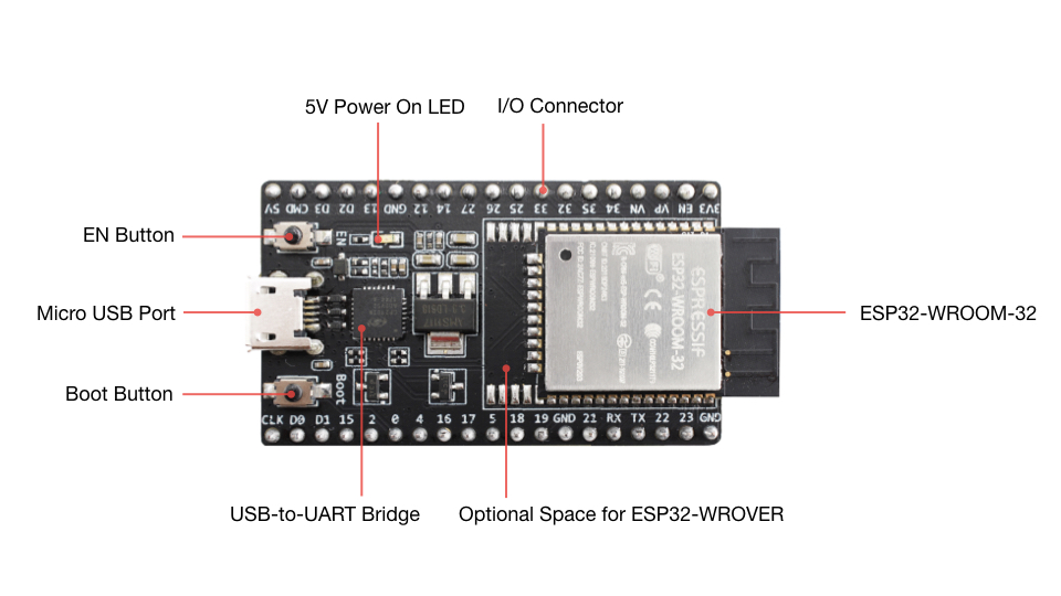
Voici les principaux composants, interfaces et contrôles de la carte ESP32-DevKitC V4 :
Composants essentiels
ESP32-WROOM-32 : Un module avec l'ESP32 comme cœur. Pour plus d'informations, consultez la fiche technique ESP32-WROOM-32.
EN : Bouton de réinitialisation.
Boot : Bouton de téléchargement. Maintenir Boot enfoncé puis appuyer sur EN active le mode de téléchargement du firmware via le port série.
Pont USB-UART : Une puce pont USB-UART unique offrant des taux de transfert jusqu'à 3 Mbps.
Port Micro USB : Interface USB servant à la fois d'alimentation pour la carte et d'interface de communication entre un ordinateur et le module ESP32-WROOM-32.
LED d'alimentation 5V : S'allume lorsque l'USB ou une alimentation externe 5V est connectée à la carte.
E/S : La plupart des broches du module ESP sont accessibles via les connecteurs de la carte. Vous pouvez programmer l'ESP32 pour activer de multiples fonctions comme PWM, ADC, DAC, I2C, I2S, SPI, etc.
Options d'alimentation
Il existe trois façons mutuellement exclusives d'alimenter la carte :
- Port Micro USB (alimentation par défaut)
- Broches d'alimentation 5V et GND
- Broches d'alimentation 3V3 et GND
Attention : L'alimentation doit être fournie en utilisant une seule de ces options, sinon la carte et/ou la source d'alimentation risquent d'être endommagées.
Utilisation des broches d'E/S
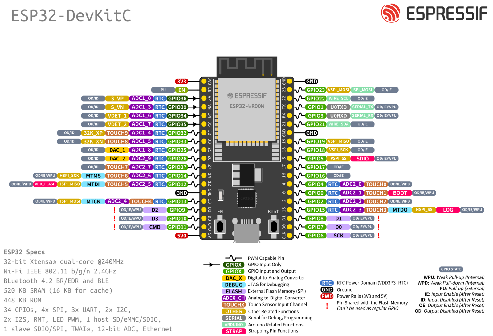
Les broches d'E/S sont disposées des deux côtés de la carte, chacune avec sa propre fonction spécifique. Consultez la documentation technique pour connaître le nom et la fonction de chaque broche.
Pourquoi choisir l'ESP32-DevKitC V4 pour vos projets ?
L'ESP32-DevKitC V4 se distingue par sa flexibilité, sa puissance de calcul et son prix abordable. Que vous soyez un débutant ou un expert en électronique, cette carte vous offre toutes les fonctionnalités nécessaires pour développer des applications IoT innovantes, des systèmes domotiques ou des projets de robotique.
Conclusion
L'ESP32-DevKitC V4 représente un excellent choix pour les développeurs cherchant une plateforme fiable et performante.
Overview
ESP32-DevKitC V4 is a small-sized ESP32-based development board produced by Espressif. Most of the I/O pins are broken out to the pin headers on both sides for easy interfacing. Developers can either connect peripherals with jumper wires or mount ESP32-DevKitC V4 on a breadboard.
To cover a wide range of user requirements, the following versions of ESP32-DevKitC V4 are available:
-
different ESP32 modules
-
male or female pin headers.
For details please refer to ESP Product Selector.
Functional Description
The following figure and the table below describe the key components, interfaces and controls of the ESP32-DevKitC V4 board.

ESP32-DevKitC V4 with ESP32-WROOM-32 module soldered
|
Key Component |
Description |
|---|---|
|
ESP32-WROOM-32 |
A module with ESP32 at its core. For more information, see ESP32-WROOM-32 Datasheet. |
|
EN |
Reset button. |
|
Boot |
Download button. Holding down Boot and then pressing EN initiates Firmware Download mode for downloading firmware through the serial port. |
|
USB-to-UART Bridge |
Single USB-UART bridge chip provides transfer rates of up to 3 Mbps. |
|
Micro USB Port |
USB interface. Power supply for the board as well as the communication interface between a computer and the ESP32-WROOM-32 module. |
|
5V Power On LED |
Turns on when the USB or an external 5V power supply is connected to the board. For details see the schematics in Related Documents. |
|
I/O |
Most of the pins on the ESP module are broken out to the pin headers on the board. You can program ESP32 to enable multiple functions such as PWM, ADC, DAC, I2C, I2S, SPI, etc. |
Power Supply Options
There are three mutually exclusive ways to provide power to the board:
-
Micro USB port, default power supply
-
5V and GND header pins
-
3V3 and GND header pins
Warning
The power supply must be provided using one and only one of the options above, otherwise the board and/or the power supply source can be damaged.
Header Block
The two tables below provide the Name and Function of I/O header pins on both sides of the board, as shown in ESP32-DevKitC V4 with ESP32-WROOM-32 module soldered.
|
No. |
Name |
Type 1 |
Function |
|---|---|---|---|
|
1 |
3V3 |
P |
3.3 V power supply |
|
2 |
EN |
I |
CHIP_PU, Reset |
|
3 |
VP |
I |
GPIO36, ADC1_CH0, S_VP |
|
4 |
VN |
I |
GPIO39, ADC1_CH3, S_VN |
|
5 |
IO34 |
I |
GPIO34, ADC1_CH6, VDET_1 |
|
6 |
IO35 |
I |
GPIO35, ADC1_CH7, VDET_2 |
|
7 |
IO32 |
I/O |
GPIO32, ADC1_CH4, TOUCH_CH9, XTAL_32K_P |
|
8 |
IO33 |
I/O |
GPIO33, ADC1_CH5, TOUCH_CH8, XTAL_32K_N |
|
9 |
IO25 |
I/O |
GPIO25, ADC1_CH8, DAC_1 |
|
10 |
IO26 |
I/O |
GPIO26, ADC2_CH9, DAC_2 |
|
11 |
IO27 |
I/O |
GPIO27, ADC2_CH7, TOUCH_CH7 |
|
12 |
IO14 |
I/O |
GPIO14, ADC2_CH6, TOUCH_CH6, MTMS |
|
13 |
IO12 |
I/O |
GPIO12, ADC2_CH5, TOUCH_CH5, MTDI |
|
14 |
GND |
G |
Ground |
|
15 |
IO13 |
I/O |
GPIO13, ADC2_CH4, TOUCH_CH4, MTCK |
|
16 |
D2 |
I/O |
GPIO9, D2 2 |
|
17 |
D3 |
I/O |
GPIO10, D3 2 |
|
18 |
CMD |
I/O |
GPIO11, CMD 2 |
|
19 |
5V |
P |
5 V power supply |
|
No. |
Name |
Type 1 |
Function |
|---|---|---|---|
|
1 |
GND |
G |
Ground |
|
2 |
IO23 |
I/O |
GPIO23 |
|
3 |
IO22 |
I/O |
GPIO22 |
|
4 |
TX |
I/O |
GPIO1, U0TXD |
|
5 |
RX |
I/O |
GPIO3, U0RXD |
|
6 |
IO21 |
I/O |
GPIO21 |
|
7 |
GND |
G |
Ground |
|
8 |
IO19 |
I/O |
GPIO19 |
|
9 |
IO18 |
I/O |
GPIO18 |
|
10 |
IO5 |
I/O |
GPIO5 |
|
11 |
IO17 |
I/O |
GPIO17 3 |
|
12 |
IO16 |
I/O |
GPIO16 3 |
|
13 |
IO4 |
I/O |
GPIO4, ADC2_CH0, TOUCH_CH0 |
|
14 |
IO0 |
I/O |
GPIO0, ADC2_CH1, TOUCH_CH1, Boot |
|
15 |
IO2 |
I/O |
GPIO2, ADC2_CH2, TOUCH_CH2 |
|
16 |
IO15 |
I/O |
GPIO15, ADC2_CH3, TOUCH_CH3, MTDO |
|
17 |
D1 |
I/O |
GPIO8, D1 2 |
|
18 |
D0 |
I/O |
GPIO7, D0 2 |
|
19 |
CLK |
I/O |
GPIO6, CLK 2 |
- 1(1,2)
-
P: Power supply; I: Input; O: Output.
- 2(1,2,3,4,5,6)
-
The pins D0, D1, D2, D3, CMD and CLK are used internally for communication between ESP32 and SPI flash memory. They are grouped on both sides near the USB connector. Avoid using these pins, as it may disrupt access to the SPI flash memory/SPI RAM.
- 3(1,2)
-
The pins GPIO16 and GPIO17 are available for use only on the boards with the modules ESP32-WROOM and ESP32-SOLO-1. The boards with ESP32-WROVER modules have the pins reserved for internal use.
Pin Layout


